
Manual


A-3
INSTALLATION
A-3
• Converter welding controls are near the arc without
long control cables, and a receptacle is provided
for an optional remote for even closer user output
control.
Simple
• Easy installation with 10 ft. (3m) work clip lead and
user preference quick-connect "pigtails" for input
and electrode weld cables.
• Easy setup with only a few intuitive welding con-
trols and lit displays; including a single
Power/Mode switch with Input level light, and a
single presettable Output Control with separate
digital meters for Amps and Volts, featuring post-
weld five second memory display.
• Easy Service with quick to replace cable "pig-
tails"and "plug-in" assembly modules, including
accessible PC boards and interchangeable "plug-
n-play" panel instruments.
Robust
• Capacity is rated for continuous operation at 350
amps in 50°C (122°F) ambient temperature, and
can be paralleled to multiply CC mode output rat-
ing.
• Overload protection is provided with electronic lim-
iting of output current, and with thermostat and
over-voltage shutdown protection which automati-
cally reset.
• Outdoor operation protected with sealed control
and power electronics compartments, with sealed
interconnections, housing "potted" circuit boards,
and using "Central-Air" cooling with "Fan-As-
Needed" for less dirt intake.
• Handling (and mishandling protection) is enhanced
with light, but durably designed, aluminum con-
struction with front to back, top and bottom, han-
dles (also serving as "roll bar" and skid), and a
sheetmetal shell attached with 1/4" steel threaded
fasteners.
RECOMMENDED EQUIPMENT AND
PROCESSES
MULTI-SYSTEM POWER SOURCE
The Multi-Source 40KW 80VDC buss power source
(K1752-1) is recommended for use in the Multi-Weld
system. However, other DC power sources capable of
supplying the required system buss current, at above
60 volts, may be used. It is recommended that this
power source have lower output inductance (choke)
such as the Lincoln Electric DC-1000, DC-655 or DC-
600 set for max. output in CC mode. The power
source output VA capacity should be 10% greater
than the sum of the max. VA of the converter arcs
which may all be simultaneously welding or gouging:
Power Source (Volts x Amps) capacity > 1.1 x Sum
of Convertersʼ (Volts x Amps) arcs
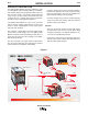
DISTRIBUTION BOX
The Multi-Weld Distribution Box (K1736-1) is avail-
able for interconnection of the Multi-System using the
same "pig-tail" connection method provided with the
RED-D-ARC MX350 converter. Six cable strain-relief
ports are provided for connection of up to (12) cables
for distribution or "daisy-chain" inter-connection to
other boxes. Four "pig-tail" leads (see below) are
included with the Box.
"PIG-TAIL" LEADS AND CONNECTORS
Accessory "pig-tail" leads and Twist-Mate connectors
are available from Lincoln for extra connections to the
RED-D-ARC MX350 or the Distribution Box:
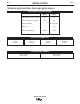
Order No. Description:
CL012705 22in.(56cm) long 2/0 (70mm2) cable
with 0.5in.(13mm) hole lug and cut-off
ends.
K852-70 Twist-Mate male insulated plug for
1/0-2/0 (50-70mm2) cable.
K852-95 Twist-Mate male insulated plug for
2/0-3/0 (70-95mm2) cable.
K1759-70 Twist-Mate female insulated recepta-
cle for 1/0-2/0 (50-70mm2) cable.
K1759-95 Twist-Mate female insulated recepta-
cle for 2/0-3/0 (70-95mm2) cable.
RED-D-ARC MX350