IM713-B RETURN TO MAIN MENU Power Wave For use with machines having Code Numbers: ® 655/R December, 2009 10630; 10863; 11410 Safety Depends on You Lincoln arc welding and cutting equipment is designed and built with safety in mind. However, your overall safety can be increased by proper installation ... and thoughtful operation on your part. DO NOT INSTALL, OPERATE OR REPAIR THIS EQUIPMENT WITHOUT READING THIS MANUAL AND THE SAFETY PRECAUTIONS CONTAINED THROUGHOUT.
i i SAFETY WARNING CALIFORNIA PROPOSITION 65 WARNINGS Diesel engine exhaust and some of its constituents are known to the State of California to cause cancer, birth defects, and other reproductive harm. The Above For Diesel Engines The engine exhaust from this product contains chemicals known to the State of California to cause cancer, birth defects, or other reproductive harm. The Above For Gasoline Engines ARC WELDING CAN BE HAZARDOUS.
ii ii SAFETY ELECTRIC SHOCK can kill. 3.a. The electrode and work (or ground) circuits are electrically “hot” when the welder is on. Do not touch these “hot” parts with your bare skin or wet clothing. Wear dry, hole-free gloves to insulate hands. 3.b. Insulate yourself from work and ground using dry insulation. Make certain the insulation is large enough to cover your full area of physical contact with work and ground.
iii iii SAFETY WELDING and CUTTING SPARKS can cause fire or explosion. 6.a. Remove fire hazards from the welding area. If this is not possible, cover them to prevent the welding sparks from starting a fire. Remember that welding sparks and hot materials from welding can easily go through small cracks and openings to adjacent areas. Avoid welding near hydraulic lines. Have a fire extinguisher readily available. 6.b.
iv SAFETY iv PRÉCAUTIONS DE SÛRETÉ Pour votre propre protection lire et observer toutes les instructions et les précautions de sûreté specifiques qui parraissent dans ce manuel aussi bien que les précautions de sûreté générales suivantes: Sûreté Pour Soudage A L’Arc 1. Protegez-vous contre la secousse électrique: a. Les circuits à l’électrode et à la piéce sont sous tension quand la machine à souder est en marche.
V V Thank You For selecting a QUALITY product by Lincoln Electric. We want you to take pride in operating this Lincoln Electric Company product ••• as much pride as we have in bringing this product to you! CUSTOMER ASSISTANCE POLICY The business of The Lincoln Electric Company is manufacturing and selling high quality welding equipment, consumables, and cutting equipment. Our challenge is to meet the needs of our customers and to exceed their expectations.
Vi Vi TABLE OF CONTENTS Page Installation .......................................................................................................Section A Technical Specifications - Power Wave® 655/r ....................................................A-1 Safety Precautions.................................................................................................A-2 Select Suitable Location ........................................................................................A-2 Lifting..........
A-1 A-1 INSTALLATION TECHNICAL SPECIFICATIONS - Power Wave® 655/r (K1519-1, K1519-2) INPUT AT RATED OUTPUT - THREE PHASE ONLY CODE NUMBERS 10630 INPUT VOLTS OUTPUT CONDITIONS INPUT IDLE POWER FACTOR EFFICIENCY CURRENT POWER @ RATED OUT- @ RATED AMPS PUT OUTPUT 600A@44V.100% 460/575V - 60HZ. 815A@44V. 60% 10863 400V - 50HZ. 550A@44V.100% 675A@44V. 60% 43/34 53/42 40 51 400 Watts Max. 84% .95 MIN. 11410 460/575V - 60HZ. 600A@44V.100% 815A@44V.
A-2 A-2 INSTALLATION SAFETY PRECAUTIONS LIFTING Read this entire installation section before you start installation. Lift the machine by the lift bail only. The lift bail is designed to lift the power source only. Do not attempt to lift the Power Wave® with accessories attached to it. WARNING ELECTRIC SHOCK can kill. • Only qualified personnel should perform this installation. • Turn the input power OFF at the disconnect switch or fuse box before working on this equipment.
A-3 A-3 INSTALLATION FIGURE A.1 - CONNECTION DIAGRAM ON CONNECTION/INPUT ACCESS DOOR INPUT SUPPLY CONNECTION DIAGRAM . Disconnect input power before inspecting or servicing machine. . Do not operate with covers removed. . Do not touch electrically live parts. . Only qualified persons should install, use or service this equipment. W / L3 V / L2 CR1 U / L1 THE LINCOLN ELECTRIC CO. CLEVELAND, OHIO U.S.A.
A-4 A-4 INSTALLATION WELDING WITH MULTIPLE Power Waves® CAUTION Special care must be taken when more than one Power Wave® is welding simultaneously on a single part. Arc blow and arc interference may occur or be magnified. Each power source requires a work lead from the work stud to the welding fixture. Do not combine all of the work leads into one lead. Performing welding in the direction away from the work leads.
A-5 A-5 INSTALLATION ELECTRODE AND WORK CABLE CONNECTIONS Connect a work lead of sufficient size and length (Per Table 1) between the proper output terminal on the power source and the work. Be sure the connection to the work makes tight metal-to-metal electrical contact. To avoid interference problems with other equipment and to achieve the best possible operation, route all cables directly to the work and wire feeder. Avoid excessive lengths and do not coil excess cable.
A-6 A-6 INSTALLATION When negative electrode polarity is required, such as in some Innershield applications, reverse the output connections at the power source (electrode cable to the negative (-) stud, and work cable to the positive (+) stud). When operating with electrode polarity negative the switch 7 must be set to ON on the Wire Feed Head PC Board. The default setting of the switch is OFF to represent positive electrode polarity.
A-7 A-7 INSTALLATION Work Voltage Sensing The Power Wave® s are shipped from the factory with the work sense lead enabled. POWER WAVE® / POWER FEED WIRE FEEDER INTERCONNECTIONS For processes requiring work voltage sensing, connect the (21) work voltage sense lead from the Power Wave® to the work. Attach the sense lead to the work as close to the weld as practical. Enable the work voltage sensing in the Power Wave® as follows: Connect the control cable between the power source and wire feeder.
A-8 A-8 INSTALLATION HIGH SPEED GEAR BOX EXTERNAL I/O CONNECTOR The Power Wave® is equipped with a port for making simple input signal connections. The port is divided into three groups: Trigger group, Cold Inch Group and Shutdown Group. Because the Power Wave® is a ‘slave’ on the DeviceNet network, the Trigger and Cold Inch Groups are disabled when the DeviceNet / Gateway is active. The shutdown group is always enabled. Shutdown 2 is used for signaling low flow in the water cooler.
A-9 A-9 INSTALLATION DIP Switch Settings and Locations Feed Head Board DIP Switch: DIP switches on the P.C. Boards allow for custom configuration of the Power Wave®.
A-10 Bank (S2): Switch 1 2 SWITCH 8 SWITCH 7 SWITCH 6 SWITCH 5 SWITCH 4 SWITCH 3 Description Devicenet Baud Rate (see table 4) TABLE 4 Prior to S24958-6 software Switch 1 switch 2 Baud rate Off off Programmable value On off 125K Off on 250K On on 500K S24958-6 and later software Switch 1 switch 2 Baud rate Off off 125K Off on 250K On off 500K On on Programmable value Bank (S2): Switch 3 Thru 8 Description Devicenet Mac ID (see table 5) TABLE 5 SWITCH 8 SWITCH 7 SWITCH 6 SWITCH 5 SWITCH 4 SWITCH 3 0 1
B-1 OPERATION SAFETY PRECAUTIONS Read this entire section of operating instructions before operating the machine. WARNING ELECTRIC SHOCK can kill. • Unless using cold feed feature, when feeding with gun trigger, the electrode and drive mechanism are always electrically energized and could remain energized several seconds after the welding ceases. • Do not touch electrically live parts or electrodes with your skin or wet clothing. • Insulate yourself from the work and ground.
B-2 OPERATION GRAPHIC SYMBOLS THAT APPEAR ON THIS MACHINE OR IN THIS MANUAL INPUT POWER SMAW ON GMAW OFF FCAW HIGH TEMPERATURE GTAW MACHINE STATUS U0 OPEN CIRCUIT VOLTAGE CIRCUIT BREAKER U1 INPUT VOLTAGE WIRE FEEDER U2 OUTPUT VOLTAGE POSITIVE OUTPUT I1 INPUT CURRENT NEGATIVE OUTPUT I2 OUTPUT CURRENT 3 PHASE INVERTER PROTECTIVE GROUND INPUT POWER THREE PHASE WARNING DIRECT CURRENT POWER WAVE® 655/R B-2
B-3 OPERATION B-3 GENERAL DESCRIPTION RECOMMENDED EQUIPMENT The Power Wave® power source is designed to be a part of a modular, multi-process welding system. Depending on configuration, it can support constant current, constant voltage, and pulse welding modes. • Automatic Operation All welding programs and procedures are set through software for the robotic Power Wave® s. FAUN robots equipped with RJ-3 controllers may communicate directly to the Power Wave®.
B-4 B-4 OPERATION CASE FRONT CONTROLS All operator controls and adjustments are located on the case front of the Power Wave®. (See Figure B.1) 1. POWER SWITCH: Controls input power to the Power Wave®. 2. STATUS LIGHT: A two color light that indicates system errors. Normal operation is a steady green light. Error conditions are indicated per table 4. NOTE: The robotic Power Wave’s® status light will flash green, and sometimes red and green, for up to one minute when the machine is first turned on.
B-5 OPERATION CONSTANT VOLTAGE WELDING For each wire feed speed, a corresponding voltage is preprogrammed into the machine through special software at the factory. The preprogrammed voltage is the best average voltage for a given wire feed speed. With synergic programs, when the wire feed speed changes the Power Wave® will automatically adjust the voltage correspondingly. Wave control adjusts the inductance of the waveshape. (This adjustment is often referred to as "pinch".
B-6 OPERATION PULSE WELDING Pulse welding procedures are set by controlling an overall "arc length" variable. When pulse welding, the arc voltage is highly dependent upon the waveform. The peak current, back ground current, rise time, fall time and pulse frequency all affect the voltage. The exact voltage for a given wire feed speed can only be predicted when all the pulsing waveform parameters are known. Using a preset voltage becomes impractical, and instead the arc length is set by adjusting "trim".
C-1 ACCESSORIES OPTIONAL EQUIPMENT C-1 * Water Flow Sensor (K1536-1) FACTORY INSTALLED There are no factory installed options available for the Power Wave®. FIELD INSTALLED Gas Guard Regulator (K659-1) The Gas Guard regulator is available as an optional accessory for Power Feed™ Robotic wire drive unit. Install the 5/8-18 male outlet on the regulator to the proper 5/8-18 female gas inlet on the back panel of the wire drive. Secure fitting with flow adjuster key at top.
D-1 MAINTENANCE SAFETY PRECAUTIONS WARNING ELECTRIC SHOCK can kill. • Only Qualified personnel should perform this maintenance. • Turn the input power OFF at the disconnect switch or fuse box before working on this equipment. • Do not touch electrically hot parts. ROUTINE MAINTENANCE Routine maintenance consists of periodically blowing out the machine, using a low pressure airstream, to remove accumulated dust and dirt from the intake and outlet louvers, and the cooling channels in the machine.
E-1 TROUBLESHOOTING E-1 HOW TO USE TROUBLESHOOTING GUIDE WARNING Service and Repair should only be performed by Lincoln Electric Factory Trained Personnel. Unauthorized repairs performed on this equipment may result in danger to the technician and machine operator and will invalidate your factory warranty. For your safety and to avoid Electrical Shock, please observe all safety notes and precautions detailed throughout this manual.
E-2 TROUBLESHOOTING USING THE STATUS LED TO TROUBLESHOOT SYSTEM PROBLEMS The Status LED on the power source case front can help diagnose problems down to the system component (power source, wire feeder, wire drive, etc.) level. E-2 If, for any reason, the system does not appear to be working properly, always check the color of the Status LED, and refer to the following chart to help you determine which system component (power source, wire feeder, wire drive, etc.) may be faulty.
E-3 E-3 TROUBLESHOOTING Observe all Safety Guidelines detailed throughout this manual PROBLEMS (SYMPTOMS) POSSIBLE CAUSE OUTPUT PROBLEMS Major physical or electrical damage 1. is evident when the sheet metal covers are removed. Contact your local authorized Lincoln Electric Field Service facility for technical assistance. Input fuses keep blowing, or input breaker keeps tripping. Make certain that fuses or breakers are properly sized.
E-4 E-4 TROUBLESHOOTING Observe all Safety Guidelines detailed throughout this manual PROBLEMS (SYMPTOMS) POSSIBLE CAUSE OUTPUT PROBLEMS Thermal LED is lit. 1. Fan thermostat has opened. Check for proper fan operation. (Fan should run whenever main power is on.) Check for material blocking intake or exhaust louvers, or for excessive dirt clogging cooing channels in machine. 2. Secondary rectifier thermostat has opened. After machine has cooled, reduce load, duty cycle, or both.
E-5 E-5 TROUBLESHOOTING Observe all Safety Guidelines detailed throughout this manual PROBLEMS (SYMPTOMS) POSSIBLE CAUSE OUTPUT PROBLEMS Machine often “noodle welds” (output is limited to approximately 100 amps) when running a particular procedure 1. Secondary current limit has been exceeded, and the machine has phased back to protect itself. Adjust procedure or reduce load to lower current draw from the machine. Machine won’t produce full output. 1.
E-6 E-6 TROUBLESHOOTING Observe all Safety Guidelines detailed throughout this manual PROBLEMS (SYMPTOMS) POSSIBLE CAUSE RECOMMENDED COURSE OF ACTION WELDING PROBLEMS The PowerWave is triggered to weld, 1. Check for fault signals from the I/O connector. Possible faults are but there is no output. lack of water flow/ water flow turned off. The feeder will not cold inch wire 1. Check for fault signals from the I/O connector. Possible faults are lack of water flow/ water cooler turned off.
E-7 TROUBLESHOOTING E-7 Observe all Safety Guidelines detailed throughout this manual ERROR CODES FOR THE POWERWAVE The following is a list of possible error codes that the PW-455 can output via the status light (see "Troubleshooting the PowerWave / Power Feed System Using the Status LED"). Indication Error Code # 11 CAN communication bus off. Probably due to excessive number of communication errors. 12 User Interface time out error. 21 Un-programmed Weld Mode.
E-8 TROUBLESHOOTING E-8 Observe all Safety Guidelines detailed throughout this manual Error Code # Indication 41 Secondary overcurrent error The secondary (weld) current limit has been exceeded. When this occurs the machine output will phase back to 100 amps, typically resulting in a condition referred to as "noodle welding" NOTE: For The Power Wave® 655 the secondary limit is 880 Amps. 43 Capacitor delta error The maximum voltage difference between the main capacitors has been exceeded.
F-1 DIAGRAMS POWER WAVE® 655/R F-1
NOTE: This diagram is for reference only. It may not be accurate for all machines covered by this manual. The specific diagram for a particular code is pasted inside the machine on one of the enclosure panels. If the diagram is illegible, write to the Service Department for a replacement. Give the equipment code number.
NOTE: This diagram is for reference only. It may not be accurate for all machines covered by this manual. The specific diagram for a particular code is pasted inside the machine on one of the enclosure panels. If the diagram is illegible, write to the Service Department for a replacement. Give the equipment code number.
F-4 PIN, LEAD CONNECTOR DIAGRAMS TABLE 1 INTERFACE CONNECTOR S6 Pin A B C D E F G H I J K L M N P R S T U V W X Lead # 841 844 842 843 845 846 847 Pin 3 Lead # 21A 67B 539 541 521 522 855A Function +15vdc Tach voltage Tach common Tach 1A differential signal Tach 1B differential signal Tach 2A differential signal Tach 2B differential signal Single Tach Input Reserved for future use Voltage sense lead Motor "+" Motor "-" Reserved for future use Reserved for future use +40vdc for solenoid solenoid inp
F-5 F-5 CONNECTION DIAGRAM Hard Automation and Electrode Positive Configuration TO SHIELDING GAS DEVICENET CABLE DEVICENET CABLE TO PLC/CONTROLLER TO PLC/CONTROLLER ELECTRODE LEAD ELECTRODE LEAD CABLE K1795 CONTROL CONTROL CABLE K1795 - SHIELDING GAS + WATERARC COOL COOLER 40 POWER CORD POWER CO NNECT ION WATER CONNECTIONS WATERCOOLED TORCH WORK SENSE LEAD K940 CONNECTION DIAGRAM, HARD AUTOMATION POWER WAVE® 655/R
F-6 F-6 CONNECTION DIAGRAM Robotic Set Up, Electrode Positive, CV/Pulse Configuration CONTROL CABLE K1805-1 CONTROL CABLE K1805-1 K1804-1 CONTROL CABLE OR K1804-2 AND ANY K1795 CONTROL CABLE User User supplied supplied electrode electrode lead lead POWERWAVE DEVICENET CABLE User supplied User work supplied lead work lead K1796 COAXIAL WELD CABLE WORK SENSE LEAD K940 POWER WAVE® 655/R +
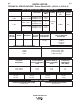
POWER WAVE® 655/R 19.00 12.35 19.16 19.90 9.48 22.63 23.12 23.51 26.10 3.47 6.75 12.90 4.21 10° 32.88 14.62 M18241 A.
NOTES POWER WAVE® 655/R
● Do not touch electrically live parts or WARNING Spanish AVISO DE PRECAUCION French ATTENTION German WARNUNG Portuguese ATENÇÃO ● Keep flammable materials away. ● Wear eye, ear and body protection. ● Mantenga el material combustible ● Protéjase los ojos, los oídos y el electrode with skin or wet clothing. ● Insulate yourself from work and ground. ● No toque las partes o los electrodos bajo carga con la piel o ropa mojada. ● Aislese del trabajo y de la tierra.
● Keep your head out of fumes. ● Use ventilation or exhaust to ● Turn power off before servicing. ● Do not operate with panel open or guards off. remove fumes from breathing zone. ● Los humos fuera de la zona de res- piración. ● Mantenga la cabeza fuera de los humos. Utilice ventilación o aspiración para gases. ● Gardez la tête à l’écart des fumées. ● Utilisez un ventilateur ou un aspira- ● Desconectar el cable de ali- mentación de poder de la máquina antes de iniciar cualquier servicio.
• World's Leader in Welding and Cutting Products • • Sales and Service through Subsidiaries and Distributors Worldwide • Cleveland, Ohio 44117-1199 U.S.A. TEL: 216.481.8100 FAX: 216.486.1751 WEB SITE: www.lincolnelectric.