RETURN TO MAIN MENU POWER WAVE For use with machines having Code Numbers: ™ IM718 AC/DC June 2002 10849 Safety Depends on You Lincoln arc welding and cutting equipment is designed and built with safety in mind. However, your overall safety can be increased by proper installation ... and thoughtful operation on your part. DO NOT INSTALL, OPERATE OR REPAIR THIS EQUIPMENT WITHOUT READING THIS MANUAL AND THE SAFETY PRECAUTIONS CONTAINED THROUGHOUT.
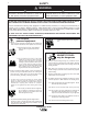
i i SAFETY WARNING CALIFORNIA PROPOSITION 65 WARNINGS Diesel engine exhaust and some of its constituents are known to the State of California to cause cancer, birth defects, and other reproductive harm. The Above For Diesel Engines The engine exhaust from this product contains chemicals known to the State of California to cause cancer, birth defects, or other reproductive harm. The Above For Gasoline Engines ARC WELDING CAN BE HAZARDOUS.
ii ii SAFETY ARC RAYS can burn. ELECTRIC SHOCK can kill. 3.a. The electrode and work (or ground) circuits are electrically “hot” when the welder is on. Do not touch these “hot” parts with your bare skin or wet clothing. Wear dry, hole-free gloves to insulate hands. 3.b. Insulate yourself from work and ground using dry insulation. Make certain the insulation is large enough to cover your full area of physical contact with work and ground.
iii iii SAFETY WELDING SPARKS can cause fire or explosion. 6.a. Remove fire hazards from the welding area. If this is not possible, cover them to prevent the welding sparks from starting a fire. Remember that welding sparks and hot materials from welding can easily go through small cracks and openings to adjacent areas. Avoid welding near hydraulic lines. Have a fire extinguisher readily available. 6.b.
iv SAFETY PRÉCAUTIONS DE SÛRETÉ Pour votre propre protection lire et observer toutes les instructions et les précautions de sûreté specifiques qui parraissent dans ce manuel aussi bien que les précautions de sûreté générales suivantes: Sûreté Pour Soudage A L’Arc 1. Protegez-vous contre la secousse électrique: a. Les circuits à l’électrode et à la piéce sont sous tension quand la machine à souder est en marche.
v v Thank You for selecting a QUALITY product by Lincoln Electric. We want you to take pride in operating this Lincoln Electric Company product ••• as much pride as we have in bringing this product to you! Please Examine Carton and Equipment For Damage Immediately When this equipment is shipped, title passes to the purchaser upon receipt by the carrier.
vi vi TABLE OF CONTENTS Page Installation .......................................................................................................Section A Technical Specifications - POWER WAVE AC/DC ...............................................A-1 Safety Precautions.................................................................................................A-2 Select Suitable Location ........................................................................................A-2 Lifting................
A-1 A-1 INSTALLATION TECHNICAL SPECIFICATIONS - POWER WAVE AC/DC (K1860-1) INPUT AT RATED OUTPUT - THREE PHASE ONLY INPUT VOLTS 50/60HZ. 3 PHASE OUTPUT CONDITIONS INPUT CURRENT AMPS IDLE POWER POWER FACTOR @ RATED OUPUT EFFICIENCY @ RATED OUPUT 460/500/575V 500A@40V.100% 31/29/25 800 Watts Max. .95 MIN. 84% OUTPUT OPEN PULSE CURRENT PULSE CIRCUIT RANGE FREQUENCY VOLTAGE VOLTAGE RANGE DC 90VDC 20-500 PULSE AND BACKGROUND TIME RANGE AUXILIARY POWER (CIRCUIT BREAKER PROTECTED) 0.
A-2 A-2 INSTALLATION SAFETY PRECAUTIONS LIFTING Read this entire installation section before you start installation. Lift the machine by the lift bail only. The lift bail is designed to lift the power source only. Do not attempt to lift the Power Wave with accessories attached to it. WARNING ELECTRIC SHOCK can kill. STACKING • Only qualified personnel should perform this installation. • Turn the input power OFF at the disconnect switch or fuse box before working on this equipment.
A-3 INSTALLATION A-3 FIGURE A.1 - CONNECTION DIAGRAM ON CONNECTION/INPUT ACCESS DOOR Do not operate with covers removed Disconnect input power before servicing Do not touch electrically live parts XA Only qualified persons should install, use or service this equipment NOTE: Turn main input power to the machine OFF before performing connection procedure. Failure to do so will result in damage to the machine.
A-4 A-4 INSTALLATION WELDING WITH MULTIPLE UNSYNCHRONIZED POWER WAVES CAUTION Special care must be taken when more than one Power Wave is welding unsynchronized on a single part. Arc blow and arc interference may occur or be magnified. Each power source requires a work lead to the work stud to the welding fixture. Do not combine all of the work leads into one lead. Performing welding in the direction away from the work leads.
A-5 A-5 INSTALLATION MULTIPLE UNSYNCHRONIZED ARC SENSE LEAD AND WORK LEAD PLACEMENT GUIDELINES BAD Power Source #1 fl Current flow from Arc #1 affects sense lead #2 fl Current flow from Arc #2 affects sense lead #1 fl Neither sense lead picks up the correct work voltage, causing starting and welding arc instability.
A-6 A-6 INSTALLATION ELECTRODE AND WORK CABLE CONNECTIONS Due to the PowerWave AC/DC’s ability to produce either a DC positive, DC negative or AC output the electrode and work connections do not need to be reversed for the different polarities. Additionally no DIP switch changes are required to switch between the different polarities. All of this is controlled internally by the Power Wave AC/DC.
A-7 A-7 INSTALLATION VOLTAGE SENSING The best arc performance occurs when the PowerWave AC/DC has accurate data about the arc conditions. Depending upon the process, inductance within the electrode and work lead cables can influence the voltage apparent at the studs of the welder. Voltage sense leads improve the accuracy of the arc conditions and can have a dramatic effect on performance. Sense Lead Kits (K490-series) are available for this purpose.
A-8 A-8 INSTALLATION CONTROL CABLE CONNECTIONS BETWEEN POWER SOURCE AND WIREFEEDER Connect the control cable between the power source and wire feeder. The wire feeder connection on the PowerWave AC/DC is located under the spring loaded output cover, on the case front. The control cable is keyed and polarized to prevent improper connect.
A-9 A-9 INSTALLATION HIGH SPEED GEAR BOX EXTERNAL I/O CONNECTOR The Power Wave is equipped with a terminal strip for making simple input signal connections. The terminal strip is located underneath the spring-loaded cover. It is divided into three groups: Trigger group, Cold Inch Group and Shutdown Group. Because the Power Wave is a ‘slave’ on the DeviceNet network, the Trigger and Cold Inch Groups are disabled when the DeviceNet/Gateway is active. The shutdown group is always enabled.
A-10 A-10 INSTALLATION DIP Switch Settings and Locations DIP switches on the P.C. Boards allow for custom configuration of the Power Wave. To access the DIP switches: WARNING • Turn off power at the disconnect switch. -----------------------------------------------------------------------• Remove the top four screws securing the front access panel. • Loosen, but do not completely remove, the bottom two screws holding the access panel.
A-11 A-11 INSTALLATION DEVICENET MAC ID TABLE A.5 Mac I.D.
A-12 INSTALLATION Bank S3 and S4 POWER WAVE AC/DC A-12
A-13 A-13 INSTALLATION MULTI-ARC SYSTEM DESCRIPTION The following is a general description of how the PowerWave AC/DC can be configured in a multi-arc set-up. Each welding arc may be driven by one machine or up to four machines connected in parallel. The hardware for the power source has been designed so that the power source can either operate as a master or a slave. A few DIP switches must be configured properly to set the machine’s identity.
B-1 OPERATION SAFETY PRECUATIONS Read this entire section of operating instructions before operating the machine. WARNING ELECTRIC SHOCK can kill. • Unless using cold feed feature, when feeding with gun trigger, the electrode and drive mechanism are always electrically energized and could remain energized several seconds after the welding ceases. • Do not touch electrically live parts or electrodes with your skin or wet clothing. • Insulate yourself from the work and ground.
B-2 OPERATION GRAPHIC SYMBOLS THAT APPEAR ON THIS MACHINE OR IN THIS MANUAL INPUT POWER SMAW ON GMAW OFF FCAW HIGH TEMPERATURE GTAW MACHINE STATUS U0 OPEN CIRCUIT VOLTAGE CIRCUIT BREAKER U1 INPUT VOLTAGE WIRE FEEDER U2 OUTPUT VOLTAGE POSITIVE OUTPUT I1 INPUT CURRENT NEGATIVE OUTPUT I2 OUTPUT CURRENT 3 PHASE INVERTER PROTECTIVE GROUND INPUT POWER THREE PHASE WARNING DIRECT CURRENT POWER WAVE AC/DC B-2
B-3 OPERATION DEFINITION OF WELDING TERMS NON-SYNERGIC WELDING MODES • A Non-synergic welding mode requires all welding process variables to be set by the operator. SYNERGIC WELDING MODES • A Synergic welding mode offers the simplicity of single knob control. The machine will select the correct voltage and amperage based on the wire feed speed (WFS) set by the operator.
B-4 OPERATION GENERAL DESCRIPTION The Power Wave AC/DC power source is designed to be a part of a modular welding system. Each welding arc may be driven by a single machine or by a number of machines in parallel. Additionally with the use of an external Phase Generator the phase angle and frequency of different machines can be synchronized. The Power Wave AC/DC is a high performance, digitally controlled inverter welding power source capable of complex, high-speed waveform control.
B-5 B-5 OPERATION CASE FRONT CONTROLS All operator controls and adjustments are located on the case front of the Power Wave. (See Figure B.1) 1. POWER SWITCH: Controls input power to the Power Wave. 2. STATUS LIGHT: A two color light that indicates system errors. Normal operation is a steady green light. Error conditions are indicated per table B1. 6. LEAD CONNECTOR S2 (SENSE LEAD) 7. 5-PIN ARC LINK S1 8. 5-PIN DEVICENET CONNECTOR S5 9. I / O CONNECTOR 10. NEGATIVE STUD 11. INTERFACE CONNECTOR S6 12.
B-6 OPERATION Second, find the program in the welding software that best matches the desired welding process. The standard software shipped with the Power Waves encompasses a wide range of common processes and will meet most needs. If a special welding program is desired, contact the local Lincoln Electric sales representative. To make a weld, the Power Wave needs to know the desired welding parameters. ArcLink allows full customization for exacting performance.
B-7 OPERATION CV WELDING Synergic CV: For each wire feed speed, a corresponding voltage is preprogrammed into the machine through special software at the factory. The nominal preprogrammed voltage is the best average voltage for a given wire feed speed, but may be adjusted to preference. With synergic programs, when the wire feed speed changes the Power Wave will automatically adjust the voltage correspondingly to maintain similar arc characteristics throughout the WFS range.
B-8 OPERATION PULSE WELDING Pulse welding procedures are set by controlling an overall "arc length" variable. When pulse welding, the arc voltage is highly dependent upon the waveform. The peak current, back ground current, rise time, fall time and pulse frequency all affect the voltage. The exact voltage for a given wire feed speed can only be predicted when all the pulsing waveform parameters are known. Using a preset voltage becomes impractical, and instead the arc length is set by adjusting "trim".
C-1 ACCESSORIES OPTIONAL EQUIPMENT FACTORY INSTALLED There are no factory installed options available for the Power Wave.
D-1 MAINTENANCE SAFETY PRECAUTIONS WARNING ELECTRIC SHOCK can kill. • Only Qualified personnel should perform this maintenance. • Turn the input power OFF at the disconnect switch or fuse box before working on this equipment. • Do not touch electrically hot parts. ROUTINE MAINTENANCE Routine maintenance consists of periodically blowing out the machine, using a low pressure airstream, to remove accumulated dust and dirt from the intake and outlet louvers, and the cooling channels in the machine.
E-1 TROUBLESHOOTING E-1 HOW TO USE TROUBLESHOOTING GUIDE WARNING Service and Repair should only be performed by Lincoln Electric Factory Trained Personnel. Unauthorized repairs performed on this equipment may result in danger to the technician and machine operator and will invalidate your factory warranty. For your safety and to avoid Electrical Shock, please observe all safety notes and precautions detailed throughout this manual.
E-2 E-2 TROUBLESHOOTING Observe all Safety Guidelines detailed throughout this manual PROBLEMS (SYMPTOMS) POSSIBLE AREAS OF MISADJUSTMENT(S) OUTPUT PROBLEMS Major physical or electrical damage is evident when the sheet metal covers are removed. 1. Contact your local authorized Lincoln Electric Field Service facility for technical assistance. Input fuses keep blowing, or input breaker keeps tripping. 1. Make certain that fuses or breakers are properly sized.
E-3 E-3 TROUBLESHOOTING Observe all Safety Guidelines detailed throughout this manual PROBLEMS (SYMPTOMS) Thermal LED is lit. Machine won’t weld, can’t get any output. (CR1 will not pull in.) POSSIBLE AREAS OF MISADJUSTMENT(S) OUTPUT PROBLEMS 1. Machine’s thermostat has opened. Check for proper fan operation. There are two main fans in the PowerWave AC/DC. One machine is located in the lower portion of the machine which should be running whenever the machine is on.
E-4 E-4 TROUBLESHOOTING Observe all Safety Guidelines detailed throughout this manual PROBLEMS (SYMPTOMS) POSSIBLE AREAS OF MISADJUSTMENT(S) OUTPUT PROBLEMS Machine often “noodle welds” (output is limited to approximately 100 amps) when running a particular procedure 1. Secondary current limit has been exceeded, and the machine has phased back to protect itself. Adjust procedure or reduce load to lower current draw from the machine. Auxiliary receptacle is “dead” — no auxiliary voltage . 1.
E-5 E-5 TROUBLESHOOTING Observe all Safety Guidelines detailed throughout this manual PROBLEMS (SYMPTOMS) POSSIBLE AREAS OF MISADJUSTMENTS(S) RECOMMENDED COURSE OF ACTION OUTPUT PROBLEMS General degradation of the weld performance. 1. Check for feeding problems, bad connections, excessive loops in cabling, etc.. 2. Verify weld mode is correct for processes. 3. The power source may require calibration.
E-6 TROUBLESHOOTING USING THE STATUS LED TO TROUBLESHOOT SYSTEM PROBLEMS The Power Wave is equipped with a status light if a problem occurs it is important to note the condition of the status light.Therefore, prior to cycling power to the system, check the power source status light for error sequences as noted below. E-6 Troubleshooting the Power Wave Using the Status LED The STATUS LIGHT is a two color light that indicates system errors. Normal operation is a steady green light.
E-7 TROUBLESHOOTING E-7 Observe all Safety Guidelines detailed throughout this manual ERROR CODES FOR THE POWERWAVE The following is a list of possible error codes that the Power Wave AC/DC can output via the status light (see "Troubleshooting the Power Wave / Power Feed System Using the Status LED"). Indication Error Code # 31 Primary overcurrent error.
WORK - TP1 31 POWER WAVE AC/DC 522 P 1 2 3 4 5 6 7 8 9 10 11 12 GND-B GND-A 851 852 853 854 855 856 857 858 859 860 861 862 12 PIN CONNECTOR TO J85 TO J83 J84 J2VS SW1 POWER 2B 1W 33 31 AC N.A. THERMAL LED (Y) TO J7 N.K. STATUS LED (R/G) TO J7 AC TO CB3 612B 886 LOAD LINE A.
POWER WAVE AC/DC FRONT OF MACHINE C1 206B 36 39 N.E. CONNECT TO POWER RESEPTACLE IN POWER SOURCE N.D. CONNECT TO OUTPUT STUD IN POWER SOURCE (CENTERTAP CONNECTION) N.C. CONNECT TO 206A IN POWER SOURCE (VOLTAGE FEEDBACK) N.B. CONNECT TO OUTPUT RECTIFIER HEATSINK IN POWER SOURCE N.A. N.A. 2.7 10W 2.7 10W 2.7 10W .022 800V .022 800V .022 800V 37 38 Thermostat 317 B2, B5 J15 38 B3, B6 B1, B4 37 316 N.D.
F-3 PIN, LEAD CONNECTOR SETUPS F-3 Table F.
F-4 F-4 CONNECTION DIAGRAM Robotic Set Up, Electrode Positive, CV/Pulse Configuration CONTROL CABLEK1805-1 K1805-1 CONTROL CABLE K1804-1 CONTROL CABLE OR K1804-2 AND ANY K1795 CONTROL CABLE User supplied User supplied electrode lead electrode lead POWERWAVE DEVICENET CABLE User supplied User supplied work lead work lead K1796 COAXIAL WELD CABLE WORK SENSE LEAD K940 POWER WAVE AC/DC +
18.80 19.16 19.83 9.45 34.96 37.46 33.08 14.62 XA DIMENSION PRINT POWER WAVE AC/DC L11656 .96 .
NOTES POWER WAVE AC/DC
NOTES POWER WAVE AC/DC
Now Available...12th Edition The Procedure Handbook of Arc Welding New Lessons in Arc Welding This printing will go fast so don’t delay. Place your order now using the coupon below. Lessons, simply written, cover manipulatory techniques; machine and electrode characteristics; related subjects, such as distortion; and supplemental information on arc welding applications, speeds and costs. Practice materials, exercises, questions and answers are suggested for each lesson.
● Do not touch electrically live parts or WARNING Spanish AVISO DE PRECAUCION French ATTENTION German WARNUNG Portuguese ATENÇÃO ● Keep flammable materials away. ● Wear eye, ear and body protection. ● Mantenga el material combustible ● Protéjase los ojos, los oídos y el electrode with skin or wet clothing. ● Insulate yourself from work and ground. ● No toque las partes o los electrodos bajo carga con la piel o ropa mojada. ● Aislese del trabajo y de la tierra.
● Keep your head out of fumes. ● Use ventilation or exhaust to ● Turn power off before servicing. ● Do not operate with panel open or guards off. remove fumes from breathing zone. ● Los humos fuera de la zona de res- piración. ● Mantenga la cabeza fuera de los humos. Utilice ventilación o aspiración para gases. ● Gardez la tête à l’écart des fumées. ● Utilisez un ventilateur ou un aspira- ● Desconectar el cable de ali- mentación de poder de la máquina antes de iniciar cualquier servicio.
• World's Leader in Welding and Cutting Products • • Sales and Service through Subsidiaries and Distributors Worldwide • Cleveland, Ohio 44117-1199 U.S.A. TEL: 216.481.8100 FAX: 216.486.1751 WEB SITE: www.lincolnelectric.