RETURN TO MAIN MENU IM771-C POWER WAVE 455M/STT ® For use with machines having Code Numbers: ® April 2013 10957,11153, 11877,11944 Safety Depends on You Lincoln arc welding and cutting equipment is designed and built with safety in mind. However, your overall safety can be increased by proper installation ... and thoughtful operation on your part. DO NOT INSTALL, OPERATE OR REPAIR THIS EQUIPMENT WITHOUT READING THIS MANUAL AND THE SAFETY PRECAUTIONS CONTAINED THROUGHOUT.
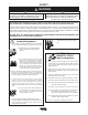
i i SAFETY WARNING CALIFORNIA PROPOSITION 65 WARNINGS Diesel engine exhaust and some of its constituents are known to the State of California to cause cancer, birth defects, and other reproductive harm. The Above For Diesel Engines The engine exhaust from this product contains chemicals known to the State of California to cause cancer, birth defects, or other reproductive harm. The Above For Gasoline Engines ARC WELDING CAN BE HAZARDOUS.
SAFETY ii ELECTRIC SHOCK can kill. 3.a. The electrode and work (or ground) circuits are electrically “hot” when the welder is on. Do not touch these “hot” parts with your bare skin or wet clothing. Wear dry, hole-free gloves to insulate hands. 3.b. Insulate yourself from work and ground using dry insulation. Make certain the insulation is large enough to cover your full area of physical contact with work and ground.
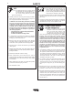
iii iii SAFETY WELDING and CUTTING SPARKS can cause fire or explosion. 6.a. Remove fire hazards from the welding area. If this is not possible, cover them to prevent the welding sparks from starting a fire. Remember that welding sparks and hot materials from welding can easily go through small cracks and openings to adjacent areas. Avoid welding near hydraulic lines. Have a fire extinguisher readily available. 6.b.
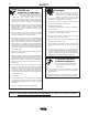
iv SAFETY PRÉCAUTIONS DE SÛRETÉ Pour votre propre protection lire et observer toutes les instructions et les précautions de sûreté specifiques qui parraissent dans ce manuel aussi bien que les précautions de sûreté générales suivantes: Sûreté Pour Soudage A LʼArc 1. Protegez-vous contre la secousse électrique: a. Les circuits à lʼélectrode et à la piéce sont sous tension quand la machine à souder est en marche.
v v Thank You for selecting a QUALITY product by Lincoln Electric. We want you to take pride in operating this Lincoln Electric Company product ••• as much pride as we have in bringing this product to you! CUSTOMER ASSISTANCE POLICY The business of The Lincoln Electric Company is manufacturing and selling high quality welding equipment, consumables, and cutting equipment. Our challenge is to meet the needs of our customers and to exceed their expectations.
vi vi TABLE OF CONTENTS Page Installation .......................................................................................................Section A Technical Specifications ......................................................................................A-1 Safety Precautions.................................................................................................A-2 Select Suitable Location ........................................................................................
vii vii TABLE OF CONTENTS Page Troubleshooting ..............................................................................................Section E How to use Troubleshooting Guide .......................................................................E-1 Using the Status LED to Troubleshoot System Problems .....................................E-2 Error Codes For Power Waves..............................................................................E-3 Troubleshooting Guide..........................
A-1 A-1 INSTALLATION TECHNICAL SPECIFICATIONS - POWER WAVE 455M/STT (K2203-1) ® ® INPUT AT RATED OUTPUT - THREE PHASE ONLY INPUT VOLTS OUTPUT CONDITIONS INPUT CURRENT AMPS 208/230/460/575V - 60HZ. 450A@38V.100% 570A@43V. 60% 58/53/25/22 82/78/37/31 200/220/440/575V - 50HZ. 400A@36V.100% 500A@40V. 60% 49/45/23/18 67/61/31/25 IDLE POWER POWER FACTOR @ RATED OUTPUT EFFICIENCY @ RATED OUTPUT 400 Watts Max. .95 MIN.
A-2 A-2 INSTALLATION SAFETY PRECAUTIONS Read this entire installation section before you start installation. WARNING LIFTING Lift the machine by the lift bail only. The lift bail is designed to lift the power source only. Do not attempt to lift the Power Wave with accessories attached to it. ELECTRIC SHOCK can kill. STACKING • Only qualified personnel should perform this installation. • Turn the input power OFF at the Power Wave machines can be stacked to a maximum of 3 high.
A-3 A-3 INSTALLATION INPUT SUPPLY CONNECTION DIAGRAM WARNING . Disconnect input power before inspecting or servicing machine. . ELECTRIC . SHOCK CAN KILL VOLTAGE = 200-208V W / L3 V / L2 200-208V CR1 220-230V U / L1 440-460V Do not operate with covers removed. 'A' 550-575V Do not touch electrically live parts. Only qualified persons should install, use or service this equipment. .
A-4 A-4 INSTALLATION CABLE INDUCTANCE, AND ITS EFFECTS ON PULSE WELDING For Pulse Welding processes, cable inductance will cause the welding performance to degrade. For the total welding loop length less than 50 feet, traditional welding cables may be used without any effects on welding performance. For the total welding loop length greater than 50 feet, the K1796 Coaxial Welding Cables are recommended.
A-5 A-5 INSTALLATION Enable the voltage sense leads as follows: TABLE A.
A-6 A-6 INSTALLATION CONFIGURING THE SYSTEM For codes below 11100, consult the semi-automatic Power Feed ® instruction manual for configuration information about DIP switch settings. For codes above 11100, the power source will “Auto Map” the system eliminating most of the need to set DIP switches to configure the system. SINGLE HEAD FEEDER If a system can not be “Auto Mapped” then the status light on the power source will blink green fast and the welder output will be disabled.
A-7 A-7 INSTALLATION ALTERNATE ALTERNA TE HARD AUT AUTOMA OMATION TION APPLICA APPLICATION TION (using a UI, WD Module, and PF-10R) POWER WAVE W VE 455M/STT ® ® PF-10R WIRE DRIVE MODULE (FH1) Combination Hard Automation Application (w/ Semi-Auto, Wire Drive Module, and PF10R) Power Wave 455M/STT Dual Head ® PF10R ® Wire Drive Module (FH1) System that is NOT “Auto Mappable”: Dual Head Boom Feeder (using two single heads) Power Wave® 455M/STT® Dual Head FH1 FH2 In this case the individual
A-8 A-8 INSTALLATION WELDING WITH MULTIPLE POWER WAVES ® CAUTION Special care must be taken when more than one Power Wave® is welding simultaneously on a single part. Arc blow and arc interference may occur or be magnified. -----------------------------------------------------------------------Each power source requires a work lead from the work stud to the welding fixture. Do not combine all of the work leads into one lead.
A-9 A-9 INSTALLATION MULTIPLE ARC UNSYNCHRONIZED SENSE LEAD AND WORK LEAD PLACEMENT GUIDELINES Power Source #1 BAD Ø Current flow from Arc #1 affects sense lead #2 Ø Current flow from Arc #2 affects sense lead #1 Ø Neither sense lead picks up the correct work voltage, causing starting and welding arc instability.
A-10 A-10 INSTALLATION I / O RECEPTACLE SPECIFICATIONS TABLE 3 WIRE FEEDER RECEPTACLE S1 PIN LEAD# FUNCTION A 53 Communication Bus L B 54 Communication Bus H C 67A Electrode Voltage Sense D 52 0vdc E 51 +40vdc TABLE 4 VOLTAGE SENSE RECEPTACLE S2 PIN LEAD# FUNCTION 3 21A Work Voltage Sense TABLE 5 RS232 RECEPTACLE S3 PIN LEAD# FUNCTION 2 253 RS232 Receive 3 254 RS232 Transmit 4 # S3 Pin5 5 # S3 Pin4 6 ## S3 Pin20 20 ## S3 Pin6 7 251 RS232 Common switch 7 off (default) auto mapping auto mapping enable o
B-1 OPERATION SAFETY PRECAUTIONS Read this entire section of operating instructions before operating the machine. WARNING ELECTRIC SHOCK can kill. • Do not touch electrically live parts or electrodes with your skin or wet clothing. • Insulate yourself from the work and ground. • Always wear dry insulating gloves. • Do not use AC welder if your clothing, gloves or work area is damp or if working on, under or inside workpiece. Use the following equipment: -DC manual (stick) welder.
B-2 OPERATION GRAPHIC SYMBOLS THAT APPEAR ON THIS MACHINE OR IN THIS MANUAL INPUT POWER SMAW ON GMAW OFF FCAW HIGH TEMPERATURE GTAW MACHINE STATUS U0 OPEN CIRCUIT VOLTAGE CIRCUIT BREAKER U1 INPUT VOLTAGE WIRE FEEDER U2 OUTPUT VOLTAGE POSITIVE OUTPUT I1 INPUT CURRENT NEGATIVE OUTPUT I2 OUTPUT CURRENT 3 PHASE INVERTER PROTECTIVE GROUND INPUT POWER WARNING OR CAUTION THREE PHASE DIRECT CURRENT POWER WAVE® 455M/STT® B-2
B-3 OPERATION DEFINITION OF WELDING TERMS SMAW • Shielded Metal Arc welding NON-SYNERGIC WELDING MODES SW • Stud Arc Welding • A Non-synergic welding mode requires all welding process variables to be set by the operator. SYNERGIC WELDING MODES • A Synergic welding mode offers the simplicity of single knob control. The machine will select the correct voltage and amperage based on the wire feed speed (WFS) set by the operator.
B-4 B-4 OPERATION GENERAL DESCRIPTION The Power Wave semi-automatic power source is designed to be a part of a modular, multi-process welding system. Depending on configuration, it can support constant current, constant voltage, STT® and pulse welding modes. ® The Power Wave ® power source is designed to be used with the semi automatic family of Power Feed® wire feeders, operating as a system.
B-5 B-5 OPERATION FIGURE B.1 CASE FRONT CONTROLS All operator controls and adjustments are located on the case front of the Power Wave®. (See Figure B.1) 3 2 1. POWER SWITCH: Controls input power to the Power Wave®. 1 2. STATUS LIGHT: A two color light that indicates system errors. Normal operation is a steady green light. Error conditions are indicated, per table B.1.
B-6 OPERATION B-6 NOMINAL PROCEDURES WELDING ADJUSTMENTS The Power Wave® is designed to operate with 3/4" electrode stick-out for CV and Pulse processes. All adjustments are made on the system component known as the User Interface (Control Box), which contains the switches, knobs, and digital displays necessary to control both the Power Wave® and a Power Feed® wire feeder. Typically, the Control Box is supplied as part of the wire feeder.
B-7 OPERATION B-7 • WELDING MODE May be selected by name (CV/MIG, CC/Stick Crisp, Gouge, etc.) or by a mode number (10, 24, 71, etc.) depending on the Control Box options. Selecting a welding mode determines the output characteristics of the Power Wave® power source. For a more complete description of the welding modes available in the Power Wave®, see the explanation below. Non Synergic CV: This type of CV mode behaves more like a conventional CV power source.
B-8 OPERATION PULSE WELDING Pulse welding procedures are set by controlling an overall "arc length" variable. When pulse welding, the arc voltage is highly dependent upon the waveform. The peak current, back ground current, rise time, fall time and pulse frequency all affect the voltage. The exact voltage for a given wire feed speed can only be predicted when all the pulsing waveform parameters are known. Using a preset voltage becomes impractical, and instead the arc length is set by adjusting "trim".
B-9 STT® WELDING OPERATION The pictures illustrate the wave shape of current for the process. They are not drawn to scale, and are intended only for the purpose of showing how the variables effect the waveform. Trim in the STT® mode adjusts the tail out and background portion of the waveform. For open root processes, the tail out is fixed, and the trim affects only the background level. Trim values greater than 1.0 add more energy to the weld and make the weld puddle hotter; trim values less than 1.
C-1 ACCESSORIES OPTIONAL EQUIPMENT FACTORY INSTALLED None Available. FIELD INSTALLED Work Voltage Sense Lead Kit, K940 Dual Cylinder Undercarriage, K1570-1. * Gas Guard Regulator, K659-1 Coaxial welding Cable, K1796 Power Wave® Water Cooler, K1767-1 * Water Flow Sensor, K1536-1 Wire Drive Interface Module, K2205-1 DeviceNet interface Module, K2206-1 Ethernet Interface Module, K2207-1 *The Dual Cylinder Undercarriage, K1570-1 is not compatible in combination with the Power Wave ® Water Cooler K1767-1.
D-1 MAINTENANCE SAFETY PRECAUTIONS WARNING ELECTRIC SHOCK can kill. • Only Qualified personnel should perform this maintenance. • Turn the input power OFF at the disconnect switch or fuse box before working on this equipment. • Do not touch electrically hot parts.
E-1 TROUBLESHOOTING E-1 HOW TO USE TROUBLESHOOTING GUIDE WARNING Service and Repair should only be performed by Lincoln Electric Factory Trained Personnel. Unauthorized repairs performed on this equipment may result in danger to the technician and machine operator and will invalidate your factory warranty. For your safety and to avoid Electrical Shock, please observe all safety notes and precautions detailed throughout this manual.
E-2 TROUBLESHOOTING USING THE STATUS LED TO TROUBLESHOOT SYSTEM PROBLEMS The Power Wave® / Power Feed® are best diagnosed as a system. Each component (power source, user interface, and feed head) has a status light, and when a problem occurs it is important to note the condition of each. In addition, errors displayed on the user interface in most cases indicate only that a problem exists in the power source, not what the problem may be.
E-3 TROUBLESHOOTING E-3 Observe all Safety Guidelines detailed throughout this manual ERROR CODES FOR THE POWERWAVE The following is a list of possible error codes that the POWER WAVE® 455M/STT® can output via the status light (see "Troubleshooting the Power Wave® / Power Feed® System Using the Status LED." If connected to a Power Feed®-10/11 these error codes will generally be accompanied by an "Err 006" or "Err 100" on the user interface display.
E-4 E-4 TROUBLESHOOTING Observe all Safety Guidelines detailed throughout this manual PROBLEMS (SYMPTOMS) POSSIBLE CAUSE OUTPUT PROBLEMS Major physical or electrical damage is evident when the sheet metal covers are removed. 1. Contact your local authorized Lincoln Electric Field Service facility for technical assistance. Input fuses keep blowing, or input breaker keeps tripping. 1. Make certain that fuses or breakers are properly sized.
E-5 E-5 TROUBLESHOOTING Observe all Safety Guidelines detailed throughout this manual PROBLEMS (SYMPTOMS) POSSIBLE CAUSE OUTPUT PROBLEMS Thermal LED is lit. 1. Fan thermostat has opened. Check for proper fan operation. (Fan should run whenever output power is on.) Check for material blocking intake or exhaust louvers, or for excessive dirt clogging cooling channels in machine. 2. Secondary rectifier or Choke thermostat has opened. After machine has cooled, reduce load, duty cycle, or both.
E-6 E-6 TROUBLESHOOTING Observe all Safety Guidelines detailed throughout this manual PROBLEMS (SYMPTOMS) POSSIBLE CAUSE OUTPUT PROBLEMS Machine often “noodle welds” (output is limited to approximately 100 amps) when running a particular procedure, especially a procedure with high WFS. 1.Secondary current limit has been exceeded, and the machine has phased back to protect itself. 2. Adjust procedure or reduce load to lower current draw from the machine. 3.
E-7 E-7 TROUBLESHOOTING Observe all Safety Guidelines detailed throughout this manual PROBLEMS (SYMPTOMS) POSSIBLE CAUSE RECOMMENDED COURSE OF ACTION General degradation of the weld per- 1.Check for feeding problems, bad formance connections, excessive loops in cabling, etc. 2. Verify weld mode is correct for processes. 3. The power source may require calibration. 4. Check the actual current displayed on the Power Feed® 10 vs. actual current measured via external meter. 5.
NOTE: This diagram is for reference only. It may not be accurate for all machines covered by this manual. The specific diagram for a particular code is pasted inside the machine on one of the enclosure panels. If the diagram is illegible, write to the Service Department for a replacement. Give the equipment code number.
F-2 F-2 CONNECTION DIAGRAM Connection Diagram Semi-automatic "Simple System" (Electrode Positive, CV/Pulse Configuration shown) POWER WAVE / STT STT STUD WIRE FEEDER TO WORK WORK SENSE CONTROL CABLE K1543 POWER WAVE® 455M/STT®
F-3 F-3 CONNECTION DIAGRAM Connection Diagram Semi-automatic "Simple System" (Electrode Positive, STT® Configuration shown) POWER WAVE / STT STT STUD WIRE FEEDER TO WORK WORK SENSE CONTROL CABLE K1543 POWER WAVE 455/STT®
POWER WAVE® 455M/STT® 19.00 12.35 19.16 19.90 9.48 22.63 23.12 23.51 26.10 3.47 6.75 12.90 4.21 10° 32.88 14.62 M18241 A.
Do not touch electrically live parts or WARNING Spanish AVISO DE PRECAUCION French ATTENTION German WARNUNG Portuguese ATENÇÃO Keep flammable materials away. Wear eye, ear and body protection. Mantenga el material combustible Protéjase los ojos, los oídos y el electrode with skin or wet clothing. Insulate yourself from work and ground. No toque las partes o los electrodos bajo carga con la piel o ropa mojada. Aislese del trabajo y de la tierra.
Keep your head out of fumes. Use ventilation or exhaust to Turn power off before servicing. Do not operate with panel open or guards off. remove fumes from breathing zone. Los humos fuera de la zona de res- piración. Mantenga la cabeza fuera de los humos. Utilice ventilación o aspiración para gases. Gardez la tête à l’écart des fumées. Utilisez un ventilateur ou un aspira- Desconectar el cable de ali- mentación de poder de la máquina antes de iniciar cualquier servicio.
Need Help? Lincoln Electric “Rapid Response” Service! Call 1.888.935.3877 to talk to a Service Representative Hours of Operation: 8:00 AM to 6:00 PM (ET) Mon. thru Fri. After hours? Use “Ask the Experts” at lincolnelectric.com A Lincoln Service Representative will contact you no later than the following business day. • For Service outside the USA: Email globalservice@lincolnelectric.com Copyright © Lincoln Global Inc.