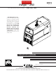
RETURN TO MAIN MENU Ranger For use with machines having Code Numbers: ® IM919 250 March, 2008 11401, 11421, 11422 Safety Depends on You Lincoln arc welding and cutting equipment is designed and built with safety in mind. However, your overall safety can be increased by proper installation ... and thoughtful operation on your part. DO NOT INSTALL, OPERATE OR REPAIR THIS EQUIPMENT WITHOUT READING THIS MANUAL AND THE SAFETY PRECAUTIONS CONTAINED THROUGHOUT.
i i SAFETY WARNING CALIFORNIA PROPOSITION 65 WARNINGS Diesel engine exhaust and some of its constituents are known to the State of California to cause cancer, birth defects, and other reproductive harm. The Above For Diesel Engines The engine exhaust from this product contains chemicals known to the State of California to cause cancer, birth defects, or other reproductive harm. The Above For Gasoline Engines ARC WELDING CAN BE HAZARDOUS.
ii ii SAFETY ARC RAYS can burn. ELECTRIC SHOCK can kill. 3.a. The electrode and work (or ground) circuits are electrically “hot” when the welder is on. Do not touch these “hot” parts with your bare skin or wet clothing. Wear dry, hole-free gloves to insulate hands. 3.b. Insulate yourself from work and ground using dry insulation. Make certain the insulation is large enough to cover your full area of physical contact with work and ground.
iii iii SAFETY WELDING and CUTTING SPARKS can cause fire or explosion. 6.a. Remove fire hazards from the welding area. If this is not possible, cover them to prevent the welding sparks from starting a fire. Remember that welding sparks and hot materials from welding can easily go through small cracks and openings to adjacent areas. Avoid welding near hydraulic lines. Have a fire extinguisher readily available. 6.b.
iv SAFETY iv PRÉCAUTIONS DE SÛRETÉ 6. Eloigner les matériaux inflammables ou les recouvrir afin de prévenir tout risque dʼincendie dû aux étincelles. Pour votre propre protection lire et observer toutes les instructions et les précautions de sûreté specifiques qui parraissent dans ce manuel aussi bien que les précautions de sûreté générales suivantes: 7. Quand on ne soude pas, poser la pince à une endroit isolé de la masse.
v v Thank You for selecting a QUALITY product by Lincoln Electric. We want you to take pride in operating this Lincoln Electric Company product ••• as much pride as we have in bringing this product to you! CUSTOMER ASSISTANCE POLICY The business of The Lincoln Electric Company is manufacturing and selling high quality welding equipment, consumables, and cutting equipment. Our challenge is to meet the needs of our customers and to exceed their expectations.
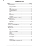
vi vi TABLE OF CONTENTS Page Installation.......................................................................................................................Section A Technical Specifications .......................................................................................................A-1 Machine Specifications ........................................................................................................A-2 Safety Precautions. .........................................................
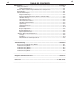
vii TABLE OF CONTENTS Maintenance......................................................................................................Section D Safety Precautions ................................................................................................D-1 Routine Maintenance ......................................................................................D-1 Kohler / Robin-Subaru Engine Maintenance Components....................................D-1 Kohler Engine ................................
A-1 A-1 INSTALLATION TECHNICAL SPECIFICATIONS - Ranger® 250 ( K1725-10, K1725-11, K1725-12) INPUT - GASOLINE ENGINE Make/Model Description Horsepower Operating Displacement cu. in.(cu. cm) @ 3600 RPM SPEED Bore x Stroke in.(mm) K1725-10, -11 Kohler CH23S OHV K1725-12 Subaru Robin EH65 OHV High 3700RPM 23 HP 2 Cylinder 4 Cycle Air Cooled Gasoline Engine 41.1 (674) 3.15x 2.64 (80x67) Starting System 12VDC Battery and starter Low Idle 2400RPM Fuel: 12gal.(45.4L) Oil: 2.0qts.(1.
A-2 A-2 INSTALLATION MACHINE SPECIFICATIONS - Ranger® 250 ( K1725-10, K1725-11, K1725-12) RECEPTACLES AND CIRCUIT BREAKERS RECEPTACLES (2) 120VAC Duplex (5-20R) (1) 120/240VAC Dual Voltage Full KVA (14-50R) AUXILIARY POWER CIRCUIT BREAKER OTHER CIRCUIT BREAKERS Two 20AMP for Two Duplex Receptacle One 50AMP for Dual Voltage (2-Pole) 20AMP for Battery Charging Circuit 15AMP for 42V Wire Feeder Power RANGER® 250
A-3 A-3 INSTALLATION LIFTING SAFETY PRECAUTIONS WARNING Do not attempt to use this equipment until you have thoroughly read the engine manufacturerʼs manual supplied with your welder. It includes important safety precautions, detailed engine starting, operating and maintenance instructions, and parts lists. -----------------------------------------------------------------------ELECTRIC SHOCK can kill. • Do not touch electrically live parts or electrode with skin or wet clothing.
A-4 A-4 INSTALLATION TOWING The recommended trailer for use with this equipment for road, in-plant and yard towing by a vehicle(1) is Lincolnʼs K957-1. If the user adapts a non-Lincoln trailer, he must assume responsibility that the method of attachment and usage does not result in a safety hazard nor damage the welding equipment. Some of the factors to be considered are as follows: 1. Design capacity of trailer vs. weight of Lincoln equipment and likely additional attachments. 2.
A-5 A-5 INSTALLATION The RANGER® 250 is shipped with the negative battery cable disconnected. Make certain that the RUN-STOP switch is in the STOP position. Remove the two screws from the rear battery tray using a screwdriver or a 3/8" socket. Attach the negative battery cable to the negative battery terminal and tighten using a 1/2" socket or wrench. The 14-pin connector is used to directly connect a wire feeder or TIG Module (K930-2) control cable.
A-6 INSTALLATION WELDING TERMINALS The Ranger® 250 is equipped with a toggle switch for selecting "hot" welding terminal when in the "WELD TERMINALS ON" position or "cold" welding terminal when in the "REMOTELY CONTROLLED" position. WELDING OUTPUT CABLES With the engine off connect the electrode and work cables to the output studs. The welding process dictates the polarity of the electrode cable. These connections should be checked periodically and tightened with a 3/4" wrench. Table A.
A-7 A-7 INSTALLATION CONNECTION OF RANGER® 250 TO PREMISES 240 VOLT GROUNDED CONDUCTOR POWER 240 Volt 60 Hz. 3-Wire Service 120 VOLT COMPANY 120 VOLT METER NEUTRAL BUS N LOAD DOUBLE POLE DOUBLE THROW SWITCH RATING TO BE THE SAME AS OR GREATER THAN PREMISES SERVICE OVERCURRENT PROTECTION. GROUND 50AMP 240 VOLT 50 AMP, 120/240 VOLT PLUG NEMA TYPE 14-50 240 VOLT PREMISES DISCONNECT AND SERVICE OVERCURRENT PROTECTION DOUBLE POLE CIRCUIT BREAKER GND N 50 AMP, 120/240 VOLT RECEPTACLE NOTE: No.
A-8 INSTALLATION CONNECTION OF LINCOLN ELECTRIC WIRE FEEDERS A-8 • Control Cable Model: Connect Control Cable between Engine Welder and Feeder. Connection of LN-7 or LN-8 to the Ranger® 250 Set the "WELD TERMINALS" switch to "REMOTELY CONTROLLED" 1. Shut the welder off. 2. Connect the LN-7 or LN-8 per instructions on the appropriate connection diagram in Section F 3. Set the "WIRE FEEDER VOLTMETER" switch to either "+" or "-" as required by the electrode being used. 4.
A-9 INSTALLATION 7. Set the "IDLE" switch to the "AUTO" position. When not welding, the Ranger® 250 engine will be at the low idle speed. If you are using an LN-25 with an internal contactor, the electrode is not energized until the gun trigger is closed. 8. When the gun trigger is closed, the current sensing circuit will cause the Ranger® 250 engine to go to the high idle speed, the wire will begin to feed and the welding process started.
B-1 B-1 OPERATION SAFETY PRECAUTIONS DESIGN FEATURES Read and understand this entire section before operating your Ranger® 250. Do not attempt to use this equipment until you have thoroughly read all operating and maintenance manuals supplied with your machine. They include important safety precautions, detailed engine starting, operating and maintenance instructions and parts lists. ENGINE OPERATION ELECTRIC SHOCK can kill.
B-2 B-2 OPERATION 15 1 14 13 12 2 11 10 3 9 8 7 6 4 5 WELDING CONTROLS: 1. OUTPUT CONTROL: The CONTROL dial provides continuous control of the welding current or welding voltage depending on the selected welding mode. This control is not active in the CC-STICK, DOWN HILL PIPE, and CV-WIRE modes when a remote control or wire feeder with remote control is connected to either the 6 pin or 14 pin Amphenol. 2.
B-3 OPERATION 4. WELD OUTPUT TERMINALS WITH FLANGE NUT: Provides a connection point for the electrode and work cables. Output stud covers provided on code 11270 and above. 5. GROUND STUD: (graphic) Provides a connection point for connecting the machine case to earth ground for the safest grounding procedure. 6. 14-PIN CONNECTOR: For attaching wire feeder control cables to the Ranger® 250. Includes contactor closure circuit, autosensing remote control circuit, and 120V and 42V power.
B-4 B-4 OPERATION CAUTION Operating the starter motor for more than 5 seconds can damage the motor. If the engine fails to start, release the switch and wait 10 seconds before operation the starter again. Do NOT push the START button while the engine is running because this can damage the ring gear and/or the starter motor.
B-5 B-5 OPERATION TIG WELDING The TOUCH START TIG setting of the MODE switch is for DC TIG (Tungsten Inert Gas) welding. To initiate a weld, the CONTROL dial is first set to the desired current and the tungsten is touched to the work. During the time the tungsten is touching the work there is very little voltage or current and, in general, no tungsten contamination. Then, the tungsten is gently lifted off the work in a rocking motion, which establishes the arc.
B-6 B-6 OPERATION ARC GOUGING The Ranger® 250 can be used for limited arc gouging. For optimal performance, set the MODE switch to CCSTICK and the ARC CONTROL to +10. Set the CONTROL knob to adjust output current to the desired level for the gouging electrode being used according to the ratings in the following table. Current Range (DC, electrode positive) Carbon Diameter 1/8" (3.2mm) The auxiliary power capacity is 10,500 Watts Peak, 9500 Watts Continuous of 60 Hz, single phase power.
C-1 ACCESSORIES RECOMMENDED OPTIONAL EQUIPMENT K957-1 HEAVY DUTY, TWO WHEEL TRAILER FOR SMALL WELDERS - For road, off-road and in-plant and yard towing. (For highway use, consult applicable federal, state and local laws regarding requirements for brakes, lights, fenders, etc.).
D-1 D-1 MAINTENANCE KOHLER ENGINE SAFETY PRECAUTIONS FREQUENCY WARNING • Have qualified personnel do all maintenance and troubleshooting work. • Turn the engine off before working inside the machine or servicing the engine. • Remove guards only when necessary to perform maintenance and replace them when the maintenance requiring their removal is complete. If guards are missing from the machine, obtain replacements from a Lincoln Distributor. (See Operating Manual Parts List.
D-2 D-2 MAINTENANCE ENGINE OIL CHANGE Drain the oil while the engine is warm to assure rapid and complete draining. • Remove the oil filler cap and dipstick. Remove the yellow cap from the oil drain valve and attach the flexible drain tube supplied with the machine. Push in and twist the drain valve counterclockwise. Pull the valve out and drain the oil into a suitable container. 4.
D-3 D-3 MAINTENANCE AIR FILTER PAPER ELEMENT 1. Loosen the cover retaining knob and remove the cover. 2. Remove the pre-cleaner from the paper element. 3. Remove the element cover nut, element cover, and paper element. 4. Do not wash the paper element or use pressurized air, as this will damage the element. Replace a dirty, bent, or damaged element with a new element. Handle new elements carefully; do not use if the sealing surfaces are bent or damaged. 5.
D-4 D-4 MAINTENANCE FUEL FILTER CLEANING THE BATTERY 1. Check the fuel filter for water accumulation or sediment. Keep the battery clean by wiping it with a damp cloth when dirty. If the terminals appear corroded, disconnect the battery cables and wash the terminals with an ammonia solution or a solution of 1/4 pound (0.12 kg) of baking soda and 1 quart (0.1 liter) of water. Be sure the battery vent plugs (if equipped) are tight so that none of the solution enters the cells. 2.
D-5 MAINTENANCE WELDER / GENERATOR MAINTENANCE STORAGE: Store the RANGER® 250 in clean, dry protected areas. CLEANING: Blow out the generator and controls periodically with low pressure air. Do this at least once a week in particularly dirty areas. BRUSH REMOVAL AND REPLACEMENT: Itʼs normal for the brushes and slip rings to wear and darken slightly. Inspect the brushes when a generator overhaul is necessary. CAUTION • Do not attempt to polish slip rings while the engine is running.
E-1 TROUBLESHOOTING E-1 HOW TO USE TROUBLESHOOTING GUIDE WARNING Service and Repair should only be performed by Lincoln Electric Factory Trained Personnel. Unauthorized repairs performed on this equipment may result in danger to the technician and machine operator and will invalidate your factory warranty. For your safety and to avoid Electrical Shock, please observe all safety notes and precautions detailed throughout this manual.
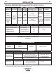
E-2 E-2 TROUBLESHOOTING Observe all Safety Guidelines detailed throughout this manual PROBLEMS (SYMPTOMS) POSSIBLE CAUSE RECOMMENDED COURSE OF ACTION Major Physical or Electrical 1. If all recommended possible Damage is Evident. areas of misadjustment have been checked and the problem persists,Contact your local Lincoln Authorized Field Service Facility. Engine will not "crank". 1. Battery is low. 2. Loose battery cable connections. 3. Faulty engine starter motor. 4.
E-3 E-3 TROUBLESHOOTING Observe all Safety Guidelines detailed throughout this manual PROBLEMS (SYMPTOMS) POSSIBLE CAUSE RECOMMENDED COURSE OF ACTION Engine will not idle down to low 1. Idler switch in High idle position. speed. 2. External load on welder or auxiliary power. 3. Faulty PC board or idler solenoid. Engine will not go to high idle when 1. Poor work lead connection to attempting to weld. work. 2. "Contactor" switch is in wrong position. 3. Faulty PC board. Low idle speed set to low.
E-4 E-4 TROUBLESHOOTING Observe all Safety Guidelines detailed throughout this manual PROBLEMS (SYMPTOMS) No welding power output. POSSIBLE CAUSE RECOMMENDED COURSE OF ACTION 1. Poor work lead connection to work. 2. "Weld Terminals" switch in wrong position. 3. Faulty PC board or welder alternator. Welder has output but no control. 1. Poor remote / control cable connection to 6 pin or 14 pin Amphenol connector. 2. Faulty remote cable or faulty wire feeder or wire feeder cable. 3.
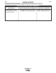
E-5 E-5 TROUBLESHOOTING Observe all Safety Guidelines detailed throughout this manual PROBLEMS (SYMPTOMS) POSSIBLE CAUSE The welding arc is “cold.” The welding arc is not stable or is not satisfactory. the engine runs normally. The auxiliary power is normal. 1. Make sure the MODE selector switch is in the correct position for the process being used. (For example, CV-WIRE, PIPE, CCSTICK.) RECOMMENDED COURSE OF ACTION 2. Make sure the electrode (wire, gas, voltage, current etc.
NOTE: This diagram is for reference only. It may not be accurate for all machines covered by this manual. The specific diagram for a particular code is pasted inside the machine on one of the enclosure panels. If the diagram is illegible, write to the Service Department for a replacement. Give the equipment code number.
F-2 DIAGRAMS RANGER® 250 F-2
F-3 DIAGRAMS RANGER® 250 F-3
F-4 DIAGRAMS RANGER® 250 F-4
F-5 DIAGRAMS RANGER® 250 F-5
F-6 DIAGRAMS RANGER® 250 F-6
RANGER® 250 + _ ELECTRODE CABLE TO WIRE FEED UNIT K595 CONTROL CABLE TO LN-8 INPUT CABLE PLUG TO WORK Keep guards in place. Keep away from moving parts. Only qualified personnel should install,use or service this equipment. Do not operate with panels open. Disconnect NEGATIVE (-) Battery lead before servicing. Do not touch electrically live parts. N.A. WELDING CABLES MUST BE OF PROPER CAPACITY FOR THE CURRENT AND DUTY CYCLE OF IMMEDIATE AND FUTURE APPLICATIONS. SEE OPERATING MANUAL. N.B.
F-8 DIAGRAMS RANGER® 250 F-8
F-9 DIAGRAMS RANGER® 250 F-9
F-10 9/03 DIAGRAMS 2 F-10 RANGER® 250
F-11 DIAGRAMS RANGER® 250 F-11
RANGER® 250 42.10 1069.5 CENTER OF GRAVITY 20.80 528.3 24.86 631.3 23.50 596.9 41.20 1046.5 TRUCK/UNDERCARRIAGE MOUNTING HOLES 2.62 66.5 17.50 444.5 15.50 393.7 19.50 495.3 10.78 273.9 29.80 756.9 33.62 854.0 36.24 920.4 M20333 C NOTE: CASE FRONT GRAPHICS MAY NOT MATCH ALL CODES. CIRCUIT BREAKERS 10.28 261.0 7.22 183.
● Do not touch electrically live parts or WARNING Spanish AVISO DE PRECAUCION French ATTENTION German WARNUNG Portuguese ATENÇÃO ● Keep flammable materials away. ● Wear eye, ear and body protection. ● Mantenga el material combustible ● Protéjase los ojos, los oídos y el electrode with skin or wet clothing. ● Insulate yourself from work and ground. ● No toque las partes o los electrodos bajo carga con la piel o ropa mojada. ● Aislese del trabajo y de la tierra.
● Keep your head out of fumes. ● Use ventilation or exhaust to ● Turn power off before servicing. ● Do not operate with panel open or guards off. remove fumes from breathing zone. ● Los humos fuera de la zona de res- piración. ● Mantenga la cabeza fuera de los humos. Utilice ventilación o aspiración para gases. ● Gardez la tête à l’écart des fumées. ● Utilisez un ventilateur ou un aspira- ● Desconectar el cable de ali- mentación de poder de la máquina antes de iniciar cualquier servicio.
• World's Leader in Welding and Cutting Products • • Sales and Service through Subsidiaries and Distributors Worldwide • Cleveland, Ohio 44117-1199 U.S.A. TEL: 216.481.8100 FAX: 216.486.1751 WEB SITE: www.lincolnelectric.