RETURN TO MAIN MENU Operator’s Manual ® RANGER 250 GXT For use with machines having Code Numbers: 11400, 11668, 11792, 12095, Register your machine: www.lincolnelectric.com/register Authorized Service and Distributor Locator: www.lincolnelectric.com/locator 11420, 11493, 11667, 11736, 11737, 11793, 11799, 11800, 12201 Need Help? Call 1.888.935.3877 to talk to a Service Representative Hours of Operation: 8:00 AM to 6:00 PM (ET) Mon. thru Fri.
THANK YOU FOR SELECTING A QUALITY PRODUCT BY LINCOLN ELECTRIC. PLEASE EXAMINE CARTON AND EQUIPMENT FOR DAMAGE IMMEDIATELY When this equipment is shipped, title passes to the purchaser upon receipt by the carrier. Consequently, Claims for material damaged in shipment must be made by the purchaser against the transportation company at the time the shipment is received. SAFETY DEPENDS ON YOU Lincoln arc welding and cutting equipment is designed and built with safety in mind.
SAFETY 1.d. Keep all equipment safety guards, covers and devices in position and in good repair.Keep hands, hair, clothing and tools away from V-belts, gears, fans and all other moving parts when starting, operating or repairing equipment. SECTION A: WARNINGS CALIFORNIA PROPOSITION 65 WARNINGS 1.e. In some cases it may be necessary to remove safety guards to perform required maintenance. Remove guards only when necessary and replace them when the maintenance requiring their removal is complete.
SAFETY ELECTRIC SHOCK CAN KILL. ARC RAYS CAN BURN. 3.a. The electrode and work (or ground) circuits are electrically “hot” when the welder is on. Do not touch these “hot” parts with your bare skin or wet clothing. Wear dry, hole-free gloves to insulate hands. 4.a. Use a shield with the proper filter and cover plates to protect your eyes from sparks and the rays of the arc when welding or observing open arc welding. Headshield and filter lens should conform to ANSI Z87. I standards. 3.b.
SAFETY WELDING AND CUTTING SPARKS CAN CAUSE FIRE OR EXPLOSION. CYLINDER MAY EXPLODE IF DAMAGED. 7.a. Use only compressed gas cylinders containing the correct shielding gas for the process used and properly operating regulators designed for the gas and pressure used. All hoses, fittings, etc. should be suitable for the application and maintained in good condition. 6.a. Remove fire hazards from the welding area. If this is not possible, cover them to prevent the welding sparks from starting a fire.
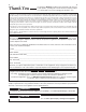
v v Thank You for selecting a QUALITY product by Lincoln Electric. We want you to take pride in operating this Lincoln Electric Company product ••• as much pride as we have in bringing this product to you! CUSTOMER ASSISTANCE POLICY The business of The Lincoln Electric Company is manufacturing and selling high quality welding equipment, consumables, and cutting equipment. Our challenge is to meet the needs of our customers and to exceed their expectations.
vi TABLE OF CONTENTS Page Installation.......................................................................................................................Section A Technical Specifications .......................................................................................................A-1 Safety Precautions ........................................................................................................A-2 Machine Grounding ...................................................................
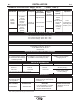
A-1 A-1 INSTALLATION TECHNICAL SPECIFICATIONS - Ranger® 250 GXT ( K2382-3, -4 and -5) INPUT - GASOLINE ENGINE Description Make/Model Kohler CH20S, CH23S, CH680 CH730 Horsepower 2 cylinder 4 Cycle Air-Cooled Gasoline Engine. Aluminum Alloy with Cast Iron Liners, Electronic Ignition Operating Speed (RPM) Displacement cu. in. (cu.cm.) High Idle 3700 23 HP @ 3600 RPM Full Load 3500 41.1(674) Low Idle 2200 44.
A-2 A-2 INSTALLATION SAFETY PRECAUTIONS WARNING Do not attempt to use this equipment until you have thoroughly read the engine manufacturerʼs manual supplied with your welder. It includes important safety precautions, detailed engine starting, operating and maintenance instructions, and parts lists. -----------------------------------------------------------------------ELECTRIC SHOCK can kill. • Do not touch electrically live parts or electrode with skin or wet clothing.
INSTALLATION A-3 3. Proper placement of the equipment on the trailer to insure stability side to side and front to back when being moved and when standing by itself while being operated or serviced. 4. Typical conditions of use, i.e., travel speed; roughness of surface on which the trailer will be operated; environmental conditions. 5. Conformance with federal, state and local laws(1) A-3 FUEL Fill the fuel tank with clean, fresh, lead-free gasoline.
A-4 A-4 INSTALLATION WELDING OUTPUT CABLES With the engine off, connect the electrode and work cables to the studs provided. These connections should be checked periodically and tightened if necessary. Loose connections will result in overheating of the output studs. When welding at a considerable distance from the welder, be sure you use ample size welding cables. Listed below are copper cable sizes recommended for the rated current and duty cycle.
A-5 INSTALLATION A-5 • LOCATION / VENTILATION The welder should be located to provide an unrestricted flow of clean, cool air to the cooling air inlets and to avoid heated air coming out of the welder recirculating back to the cooling air inlet. Also, locate the welder so that engine exhaust fumes are properly vented to an outside area. STACKING Ranger® 250 GXT machines cannot be stacked. CONNECTION OF LINCOLN ELECTRIC WIRE FEEDERS WARNING Shut off welder before making any electrical connections.
A-6 A-6 INSTALLATION WELDER OPERATION 120/240 VOLT DUAL VOLTAGE RECEPTACLE WELDER OUTPUT • Maximum Open Circuit Voltage at 3700 RPM is 80 Volts RMS. • Duty Cycle is the percentage of time the load is being applied in a 10 minute period. For example, a 60% duty cycle represents 6 minutes of load and 4 minutes of no load in a 10 minute period. Duty Cycle for the Ranger® 250 GXT is 100%.
A-7 A-7 INSTALLATION CAUTION Certain Electrical devices cannot be powered to this Product. See Table A.2 TABLE lll ELECTRICAL DEVICE USE WITH THIS PRODUCT Type Common Electrical Devices Possible Concerns Resistive Heaters, toasters, incandescent light bulbs, electric range, hot pan, skillet, coffee maker. NONE Capacitive TV sets, radios, microwaves, appliances with electrical control. Voltage spikes or high voltage regulation can cause the capacitative elements to fail.
A-8 INSTALLATION AUXILIARY POWER WHILE WELDING Simultaneous welding and power loads are permitted by following Table I. The permissible currents shown assume that current is being drawn from either the 120V or 240V supply (not both at the same time). Also, the “Output Control” is set at “10” for maximum auxiliary power. TABLE I SIMULTANEOUS WELDING AND POWER Output Selector Setting * Permissible Power Watts (Unity Power Permissible Auxiliary Current in Amperes Factor) @ 120V *-or- @ 240V Max.
A-9 INSTALLATION Figure 1 CONNECTION OF Ranger® 250 GXT TO PREMISES WIRING WARNING Connection of Ranger ® 250 GXT to premises wiring must be done by a licensed electrician and must comply with the National Electrical Code and all other applicable electrical codes.
B-1 OPERATION SAFETY PRECAUTIONS Do not attempt to use this equipment until you have thoroughly read the engine manufacturerʼs manual supplied with your welder. It includes important safety precautions, detailed engine starting, operating and maintenance instructions, and parts lists. -----------------------------------------------------------------------ELECTRIC SHOCK can kill. • Do not touch electrically live parts or electrode with skin or wet clothing.
B-2 “ B-2 OPERATION 6-PIN CONNECTOR RANGE” SWITCH The “Range” switch is used to select one of four amperage ranges with generous overlap for Stick/TIG welding, or one Wire Feed welding range. Process STICK/TIG (constant current) (4 range settings) WIRE FEED (constant voltage) (2 range setting) Range Setting Current Range 80 Max. 130 Max. 180 Max. 250 Max.
B-3 B-3 OPERATION STARTING/SHUTDOWN INSTRUCTIONS STARTING THE ENGINE STOPPING THE ENGINE Remove all welding and auxiliary power loads and allow engine to run at low idle speed for a few minutes to cool the engine. WARNING • Do not touch electrically live parts of electrode with skin or wet clothing. • Keep flammable material away. • Insulate yourself from work and ground. Wear eye, ear, and body protection. • Keep your head out of the fumes.
B-4 B-4 OPERATION WELDING PROCESS SETTINGS FOR 1% THORIATED TUNGSTEN For any electrodes the procedures should be kept within the rating of the machine. For electrode information see the appropriate Lincoln publication. STICK (CONSTANT CURRENT) WELDING Connect welding cables to the "TO WORK” and "ELECTRODE” studs. Start the engine. Set the "Polarity” switch to the desired polarity.
B-5 B-5 OPERATION SUMMARY OF WELDING PROCESSES CONTROL CABLE USED IDLE MODE ELECTRODE WHEN NOT WELDING STICK No AUTO Hot Touch electrode to work. Welding starts immediately and engine goes to high idle. WIRE FEED, LN-25 WITH INTERNAL CONTACTOR No AUTO Cold Press gun trigger, LN-25 contactor closes. Welding starts immediately and engine goes to high idle. Note: Output Control must be set above “3”.
C-1 ACCESSORIES C-1 OPTIONAL EQUIPMENT GENERAL TIG K802N Power Plug Kit K1783-4 PTA-26 TIG Torch (25 ft 2pc) K1690-1 GFCI Receptacle Kit KP509 Parts Kit K1898-1 Spark Arrester Kit K930-2 TIG Module K886-2 Canvas Cover (Large) K936-3 Control Cable for TIG Module K1737-1 All Terrain Undercarriage K937-45 TIG Module Control Cable Extension K1770-1 Factory Undercarriage K963-3 Hand Amptrol™ K1745-1 Welding Gas Cylinder, LPG Tank Holder K2635-1 Small Two-Wheel Road Trailer with Duo-Hitch K2639-1
C-2 ACCESSORIES WIRE FEEDER K2652-2-10-45 Magnum® PRO 350 Welding Gun Ready-Pak 15 ft. 035-5/64 KP1696-1 Drive Roll Kit Combination .035 in / .
D-1 D-1 MAINTENANCE SAFETY PRECAUTIONS WARNING Have qualified personnel do the maintenance work. Turn the engine off before working inside the machine. In some cases, it may be necessary to remove safety guards to perform required maintenance. Remove guards only when necessary and replace them when the maintenance requiring their removal is complete. Always use the greatest care when working near moving parts. Do not put your hands near the engine cooling blower fan.
D-2 MAINTENANCE SAE 10W-30 is recommended for general, all-temperature use, -5ºF to 104ºF (-20ºC to 40ºC). See Engine Ownerʼs Manual for more specific information on oil viscosity recommendations. AIR CLEANER AND OTHER MAINTENANCE • Air Cleaner - With normal operating conditions, the maintenance schedule for cleaning and re-oiling the foam pre-filter is every 25 hours and replacement of the air cleaner filter every 100 hours. More frequent servicing is required with dusty operating conditions.
D-3 D-3 MAINTENANCE ENGINE ADJUSTMENTS WARNING GASES FROM BATTERY can explode. • Keep sparks, flame and cigarettes away from battery. OVERSPEED IS HAZARDOUS To prevent EXPLOSION when: • INSTALLING A NEW BATTERY - disconnect negative cable from old battery first and connect to new battery last. WARNING The maximum allowable high idle speed for this machine is 3750 RPM, no load. Do NOT tamper with governor components or setting or make any other adjustments to increase the maximum speed.
E-1 TROUBLESHOOTING E-1 HOW TO USE TROUBLESHOOTING GUIDE WARNING Service and Repair should only be performed by Lincoln Electric Factory Trained Personnel. Unauthorized repairs performed on this equipment may result in danger to the technician and machine operator and will invalidate your factory warranty. For your safety and to avoid Electrical Shock, please observe all safety notes and precautions detailed throughout this manual.
E-2 E-2 TROUBLESHOOTING Observe all Safety Guidelines detailed throughout this manual PROBLEMS (SYMPTOMS) No welder output power or Auxiliary Power. POSSIBLE CAUSE RECOMMENDED COURSE OF ACTION 1. Open in miscellaneous leads. 2. Open lead in flashing or field circuit. 3. Faulty rotor. 4. Faulty Potentiometer (R1). 5. Faulty stator Field winding. 6. Faulty Field rectifier (On PCB*). 7. Faulty P.C. Board. Engine will not idle down to low speed. 1. Idler switch on High Idle.
E-3 E-3 TROUBLESHOOTING Observe all Safety Guidelines detailed throughout this manual PROBLEMS (SYMPTOMS) Engine will not go to high idle when using auxiliary power. Engine will not crank or is hard to crank. Engine shuts down. POSSIBLE CAUSE 1. No voltage signal from the current sensor. 2. Auxiliary power load less than 100 to 150 watts. 3. Faulty P.C. Board. 1. Battery will not hold a charge. Faulty Battery. 2. No or insufficient charging current. 3. Loose battery cable connection(s). 1.
F-1 NOTE: This diagram is for reference only. It may not be accurate for all machines covered by this manual. The specific diagram for a particular code is pasted inside the machine on one of the enclosure panels. If the diagram is illegible, write to the Service Department for a replacement. Give the equipment code number.
F-2 NOTE: This diagram is for reference only. It may not be accurate for all machines covered by this manual. The specific diagram for a particular code is pasted inside the machine on one of the enclosure panels. If the diagram is illegible, write to the Service Department for a replacement. Give the equipment code number.
F-3 DIAGRAMS RANGER® 250 GXT F-3
RANGER® 250 GXT 41.20 42.10 20.80 24.86 21.00 TRUCK / UNDERCARRIAGE MOUNTING HOLES 2.6 17.50 19.50 14.75 CIRCUIT RCUIT BREA EAKERS 10.78 29.88 33.62 36.24 DIMENSION PRINT M20512 B NOTE: CASE FRONT GRAPHICS MAY NOT MATCH ALL CODES. CENTER OF GRAVITY WITH OIL IN ENGINE AND EMPTY FUELTANK. 7.22 10.
RANGER® 250 GXT 41.20 1046.48 42.10 1069.46 20.80 528.28 24.86 631.33 TRUCK/UNDERCARRIAGE MOUNTING HOLES 2.6 66.55 22.00 558.8 17.50 19.50 444.5 495.3 10.75 273.05 CIRCUIT BREAKERS 10.27 260.98 7.22 183.39 10.78 273.93 29.88 758.95 33.62 853.97 NOTE: CASEFRONT GRAPHICS MAY NOT MATCH ALL CODES. CENTER OF GRAVITY WITH OIL IN ENGINE AND EMPTY FUEL TANK. DIMENSION DIAGRAM CODES 12095, 12096 A INCH MM DIMENSION PRINT M24957 36.24 920.
P-505 P-505 PARTS LIST FOR Ranger® GXT & Ranger® 250 GXT This parts list is provided as an informative guide only. It was accurate at the time of printing. These pages are only updated on the Service Navigator DVD and in Lincoln Electricʼs official Parts Book (BK-34). When ordering parts, always refer to Lincoln Electricʼs official Parts Book (BK-34) for the latest pages.
P-505-A P-505-A ILLUSTRATION OF SUB ASSEMBLIES 7 4 5 6 3 1 2 RANGER® GXT & RANGER® 250 GXT 08-03-2009
P-505-A.1 P-505-A.1 Ranger® GXT & Ranger® 250 GXT For Codes 11154, 11269, 11400, 11420 & 11493 Do Not use this Parts List for a machine if its code number is not listed. Contact the Service Department for any code numbers not listed. PAGE NO. CODE NO.
P-505-B.1 OPTIONAL EQUIPMENT LISTING P-505-B.1 Miscellaneous Options Available for your machine are listed below: # Indicates a change this printing. DESCRIPTION . . . . . . . . . . . . . . . . . . . . . . . . . . . . . . . . . . . . . . . . . . . . . . . . . . . . . . . . . . . . . . . . . . . . . . .PART NUMBER Accessory Package . . . . . . . . . . . . . . . . . . . . . . . . . . . . . . . . . . . . . . . . . . . . . . . . . . .Order K702 Spark Arrestor . . . . . . . . . . . . . . . . . . . . . . . .
P-505-B.2 # Indicates a change this printing. ITEM DESCRIPTION Harness Assembly Spark Arrestor Plug & Lead Assembly MISCELLANEOUS ITEMS P-505-B.2 (THESE ITEMS ARE NOT ILLUSTRATED) Use only the parts marked “x” in the column under the heading number called for in the model index page. PART NO. QTY.
P-505-C P-505-C Case Front Assembly 1 13 15A 14 4 15 17 9A 7 9C 8 6C 5 9B 6B 16A 6A 16B 6D 12 3B 3A 3C 11 10 RANGER® GXT & RANGER® 250 GXT 19C 19B 19A 10-04-2011
P-505-C.1 P-505-C.1 # Indicates a change this printing. Use only the parts marked “x” in the column under the heading number called for in the model index page. ITEM DESCRIPTION PART NO. QTY.
P-505-D P-505-D Control Panel Assembly 20 18C 1A 18B 6 1B 17 18A 5 3A 19A 19B 21 9 18E 5A { 4 18C18D 18C 18D 7A 20A 10 23A 8 22B 12 22A 2B 20A 11 23B 2A RANGER® GXT & RANGER® 250 GXT 08-03-2009
P-505-D.1 P-505-D.1 # Indicates a change this printing. Use only the parts marked “x” in the column under the heading number called for in the model index page. ITEM DESCRIPTION PART NO. QTY.
P-505-E P-505-E Base/Fuel Tank/Battery Assembly 10B 4H 10A 4D 4G 4F 12A 4E 4B 2A 4A 5A 5C 5D 5 { 8B 11 6B 8C 8A 5B 5C 6C 13A 6A 6D 7 2B 1 11A RANGER® GXT & RANGER® 250 GXT 08-03-2009
P-505-E.1 P-505-E.1 # Indicates a change this printing. Use only the parts marked “x” in the column under the heading number called for in the model index page. ITEM DESCRIPTION PART NO. QTY.
P-505-F P-505-F Engine Assembly 1 Supplied with 4 Engine 2 1C 1A 2A Supplied with Engine 1C 1D RANGER® GXT & RANGER® 250 GXT 1B 08-03-2009
P-505-F.1 P-505-F.1 # Indicates a change this printing. Use only the parts marked “x” in the column under the heading number called for in the model index page. ITEM DESCRIPTION PART NO. QTY.
P-505-G P-505-G Blower Baffle Assembly 10 3 7B 7A 16 17 1 RANGER® GXT & RANGER® 250 GXT 08-03-2009
P-505-G.1 P-505-G.1 # Indicates a change this printing. Use only the parts marked “x” in the column under the heading number called for in the model index page. ITEM DESCRIPTION PART NO. QTY.
P-505-H P-505-H Stator/Rotor Assembly 4A 7 1 5B 5C 5A 5E 1F 4B 5F 5D 1A 1D 1E 8A 9 1C 8 1B } 13 7A 6D 6C 6C 7B 6A 7C 11 10 12 6B RANGER® GXT & RANGER® 250 GXT 08-03-2009
P-505-H.1 P-505-H.1 # Indicates a change this printing. Use only the parts marked “x” in the column under the heading number called for in the model index page. ITEM DESCRIPTION PART NO. QTY.
P-505-J P-505-J Covers & Case Back Assembly 9B 9A 16 7 3A 8 12 4B 10 4A 14 11 2B 5A 2A 23A 17 15 6B 23 6A 17 1A 6C 15 13 21 RANGER® GXT & RANGER® 250 GXT 08-03-2009
P-505-J.1 P-505-J.1 # Indicates a change this printing. Use only the parts marked “x” in the column under the heading number called for in the model index page. ITEM DESCRIPTION PART NO. QTY.
NOTES RANGER® GXT & RANGER® 250 GXT
P-634 P-634 PARTS LIST FOR Ranger® 250 GXT This parts list is provided as an informative guide only. It was accurate at the time of printing. These pages are only updated on the Service Navigator DVD and in Lincoln Electricʼs official Parts Book (BK-34). When ordering parts, always refer to Lincoln Electricʼs official Parts Book (BK-34) for the latest pages.
P-634-A P-634-A ILLUSTRATION OF SUB ASSEMBLIES 7 4 5 6 2 3 1 RANGER® 250 GXT Oct-13
P-634-A.1 P-634-A.1 Ranger® 250 GXT For Codes: 11667, 11668, 11736, 11737, 11792, 11793, 11799, 11800, 12095, 12096, 12201 & 12202 Do Not use this Parts List for a machine if its code number is not listed. Contact the Service Department for any code numbers not listed. PAGE NO. CODE NO.
P-634-A.2 P-634-A.2 Ranger® 250 GXT For Codes: 11667, 11668, 11736, 11737, 11792, 11793, 11799, 11800, 12095, 12096, 12201 & 12202 Do Not use this Parts List for a machine if its code number is not listed. Contact the Service Department for any code numbers not listed. PAGE NO. CODE NO.
P-634-B.2 # Indicates a change this printing. ITEM DESCRIPTION Spark Arrestor Clamp MISCELLANEOUS ITEMS P-634-B.2 (THESE ITEMS ARE NOT ILLUSTRATED) Use only the parts marked “x” in the column under the heading number called for in the model index page. PART NO. QTY.
P-634-C P-634-C Case Front (Upper) 1A 57A 3A 29 21 8 7A 25A 25B 59A 58A 50 26 4A 5A 23 58A RANGER® 250 GXT Oct-13
P-634-C.1 P-634-C.1 # Indicates a change this printing. Use only the parts marked “x” in the column under the heading number called for in the model index page. ITEM DESCRIPTION PART NO. QTY.
P-634-D P-634-D Case Front (Lower) 11B 11A 12 12 13 18C 18A 25A 22 27A 36 17 35 15A 34A 16 6B 6A 18B 6E 6F 14 6D 31 28 20 19 6C 51B 51A 56 RANGER® 250 GXT Oct-13
P-634-D.1 P-634-D.1 # Indicates a change this printing. Use only the parts marked “x” in the column under the heading number called for in the model index page. ITEM DESCRIPTION PART NO. QTY.
P-634-E P-634-E Base/Fuel Tank/Battery Assembly 4C 10 4D 17E 4E 17F 17H 17G 4F 4G 17C 17D 4B 4A 17B 17F 17H 5A 17A 2A 8C 11A 8D 8A 8E 7 8B 1 13A 2B 20 5B RANGER® 250 GXT Oct-13
P-634-E.1 P-634-E.1 # Indicates a change this printing. Use only the parts marked “x” in the column under the heading number called for in the model index page. ITEM DESCRIPTION PART NO. QTY.
P-634-F P-634-F Engine Assembly 1A 2A 1E 1B 1E 1F 1C RANGER® 250 GXT Oct-13
P-634-F.1 P-634-F.1 # Indicates a change this printing. Use only the parts marked “x” in the column under the heading number called for in the model index page. ITEM DESCRIPTION PART NO. QTY. 1 2 3 4 5 6 7 8 9 1A 1A 1A 1B 1C 1D 1E 1F 1G 2A 2B 5 NSS NSS NSS S24344 CF000196 S9262-120 S9262-113 E106A-16 CF000067 G3574-4 M16999-1 M16980-1 1 1 1 2 2 2 6 2 2 1 2 1 X • • X X X X X X X X X Engine (M21300) - Kohler Engine (M22704) - Kohler Engine (M24866) - Kohler Rubber Mounting 3/8-16 x 2.
P-634-G P-634-G Blower Baffle Assembly 7A 1 3 7B 10 17 RANGER® 250 GXT Oct-13
P-634-G.1 P-634-G.1 # Indicates a change this printing. Use only the parts marked “x” in the column under the heading number called for in the model index page. ITEM DESCRIPTION PART NO. QTY.
P-634-H P-634-H Stator/Rotor Assembly 2A 2B 1A 7A 5A 5B 15A 1G 1D 1E 9A 1F 8B 8A 1B 13 12 1C 6D 6E 6F 11 10 6C 6A 6C 6B RANGER® 250 GXT Oct-13
P-634-H.1 P-634-H.1 # Indicates a change this printing. Use only the parts marked “x” in the column under the heading number called for in the model index page. ITEM DESCRIPTION PART NO. QTY.
P-634-J P-634-J Covers & Case Back Assembly 3A 9B 9A 16 25A 25B 23 7 10 4B 8 19 4A 18 14 12 11 20 2A 5A 15 6B 6A 17 15 1A 21A 6C 13 RANGER® 250 GXT Oct-13
P-634-J.1 P-634-J.1 # Indicates a change this printing. Use only the parts marked “x” in the column under the heading number called for in the model index page. ITEM DESCRIPTION PART NO. QTY.
P-634-J.2 P-634-J.2 # Indicates a change this printing. Use only the parts marked “x” in the column under the heading number called for in the model index page. ITEM DESCRIPTION PART NO. QTY.
NOTES RANGER® 250 GXT
CUSTOMER ASSISTANCE POLICY The business of The Lincoln Electric Company is manufacturing and selling high quality welding equipment, consumables, and cutting equipment. Our challenge is to meet the needs of our customers and to exceed their expectations. On occasion, purchasers may ask Lincoln Electric for advice or information about their use of our products. We respond to our customers based on the best information in our possession at that time.