RETURN TO MAIN MENU IM438-B MAGNUM COOLERS 10-I AND 20-I ™ March, 1999 For use with machines having Code Number 9743, 9745, 9984, 9986,10266 and 10268 Safety Depends on You Lincoln arc welding and cutting equipment is designed and built with safety in mind. However, your overall safety can be increased by proper installation ... and thoughtful operation on your part. DO NOT INSTALL, OPERATE OR REPAIR THIS EQUIPMENT WITHOUT READING THIS MANUAL AND THE SAFETY PRECAUTIONS CONTAINED THROUGHOUT.
i i SAFETY WARNING CALIFORNIA PROPOSITION 65 WARNINGS Diesel engine exhaust and some of its constituents are known to the State of California to cause cancer, birth defects, and other reproductive harm. The Above For Diesel Engines The engine exhaust from this product contains chemicals known to the State of California to cause cancer, birth defects, or other reproductive harm. The Above For Gasoline Engines ARC WELDING CAN BE HAZARDOUS.
ii ii SAFETY ELECTRIC SHOCK can kill. 3.a. The electrode and work (or ground) circuits are electrically “hot” when the welder is on. Do not touch these “hot” parts with your bare skin or wet clothing. Wear dry, hole-free gloves to insulate hands. 3.b. Insulate yourself from work and ground using dry insulation. Make certain the insulation is large enough to cover your full area of physical contact with work and ground.
iii iii SAFETY WELDING SPARKS can cause fire or explosion. 6.a. Remove fire hazards from the welding area. If this is not possible, cover them to prevent the welding sparks from starting a fire. Remember that welding sparks and hot materials from welding can easily go through small cracks and openings to adjacent areas. Avoid welding near hydraulic lines. Have a fire extinguisher readily available. 6.b.
iv iv SAFETY PRÉCAUTIONS DE SÛRETÉ Pour votre propre protection lire et observer toutes les instructions et les précautions de sûreté specifiques qui parraissent dans ce manuel aussi bien que les précautions de sûreté générales suivantes: Sûreté Pour Soudage A L’Arc 1. Protegez-vous contre la secousse électrique: a. Les circuits à l’électrode et à la piéce sont sous tension quand la machine à souder est en marche.
v v for selecting a QUALITY product by Lincoln Electric. We want you to take pride in operating this Lincoln Electric Company product ••• as much pride as we have in bringing this product to you! Thank You Please Examine Carton and Equipment For Damage Immediately When this equipment is shipped, title passes to the purchaser upon receipt by the carrier.
vi TABLE OF CONTENTS Page Installation .......................................................................................................Section A Technical Specifications ........................................................................................A-1 Product Description ...............................................................................................A-2 Warranty ................................................................................................................
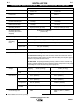
A-1 A-1 INSTALLATION TECHNICAL SPECIFICATIONS – MAGNUM COOLERS 10-I AND 20-I Model Cooler 10-I Cooler 20-I Product No. K873-1 K879-1 Input 220V 50/60 Hz 1 Phase 220V 50/60 Hz 1 Phase Current Draw at Input .75 Amps 1.25 Amps Rated Current Draw 1.0 Amps 1.6 Amps Operating Pressure 45 psi (310 kPa) (3.0 bar) 60 psi (410 kPa) (4.0 bar) Shutdown Pressure (No delay after flow is stopped) 60-65 psi (414-446 kPa) (4.0-4.4 bar) Flow Range Typical Operating Flow 0.1 to 0.8 gal/min (0.4 to 3.
A-2 INSTALLATION A-2 PRODUCT DESCRIPTION Magnum Coolers 10-I and 20-I are stand alone recirculating cooling systems designed for use with water cooled TIG, MIG, PAC (Plasma Arc Cutting) and PAW (Plasma Arc Welding) guns and torches. Additional applications include resistance welding, induction heating and water cooled fixtures such as EDM’s and small Verti-Shield dams. The connection block located at the back of the Cooler contains 5/8-18 left hand female thread.
A-3 A-3 INSTALLATION INSTALLATION The FILL CAP is at the front of the unit (C). WARNING Cap removal: While pressing the bulls-eye inward, grip the tab and remove the cap with a peeling motion. ELECTRIC SHOCK can kill. • Disconnect input power by removing plug from receptacle before working inside Cooler. • Use only grounded receptacle. • Do not remove the power cord ground prong. • Do not touch electrically “hot” parts inside Cooler.
A-4 INSTALLATION A-4 The case front sheet metal design allows for ease of access to repair all internal components. The Phillips head fasteners used to secure the casing match the style of fasteners used in the pump head and other major components. In this manner, an operator can repair all major components in the unit using just a Phillips head screwdriver.
A-5 INSTALLATION Cooler and insert the nipple into the connector nut so that the threaded end of the connector nut points away from the barbed end of the nipple. Twist the barbed end of the nipple into the hose until the shoulder of the nipple is flush with the end of the hose. Secure the hose onto the nipple with a hose clamp to insure that the connection is water tight. No water can leak from the connection if it is properly attached. Repeat the procedure for the OUTLET hose.
A-6 A-6 INSTALLATION FIGURE 3a FIGURE 3b NOTE: FOR PROPER INSTALLATION WHEN USED WITH LINCOLN K835, K840, K841 OR K842 UNDERCARRIAGES, THE RUBBER FEET MAY NEED TO BE REMOVED FROM THE BOTTOM OF THE MOUNTING BRACKET.
A-7 A-7 INSTALLATION FIGURE 3c Undercarriage Mounting Bracket Layout A POWER SOURCE HEIGHT 16.44" (417.6mm) B POWER SOURCE HEIGHT 21.50" (546.1mm) Cooler 10-I Mounting Scheme C POWER SOURCE HEIGHT 16.44" (417.6mm) D POWER SOURCE HEIGHT 21.50" (546.1mm) E POWER SOURCE HEIGHT 27.50" (698.
A-8 A-8 INSTALLATION WATER COOLED EQUIPMENT INSTALLATION NOTE: Magnum Coolers operate at 45 psi (3.0 bar) (310 kPa) of pressure for Cooler 10-I and 60 psi (4.0 bar) (414 kPa) of pressure for Cooler 20-I. When used in the demand system, the pressure in the supply hose to the water solenoid or valve can surge to 20 psi (1.4 bar) (138 kPa) above holding pressure just before shutdown. The holding pressure will be 60-65 psi (4.0-4.4 bar) (414-448 kPa).
A-9 A-9 INSTALLATION FIGURE 5 Water Cooled MIG Gun Connection COOLANT IN COOLANT OUT COOLANT COOLANT GUN CABLE FIGURE 6 Water Cooled Plasma System Connection COOLANT IN COOLANT OUT COOLANT PLASMA CUTTING POWER SOURCE AIR ELECTRODE CABLE & AIR COOLANT MAGNUM COOLER 10-I & 20-I
A-10 A-10 INSTALLATION K440-1 LN-7 GMA WIRE FEEDER WITH GAS AND WATER SOLENOID VALVE The K440-1 LN-7 GMA wire feeder is equipped with internal water lines and external connectors for attachment to a water cooled MIG gun and a Magnum Cooler. The water solenoid control of the K440-1 LN-7 GMA enables the feeder to trigger the demand system of a Magnum Cooler. (Reference Operation Section for an explanation of the Magnum Cooler demand system).
A-11 A-11 INSTALLATION K529-10 POWER INPUT CABLE WITH WATER AND GAS LINES The K529 power input cable connects from the front of a Lincoln power source to the back of LN-7 and LN-7 GMA wire feeders equipped with a water solenoid control. K529-10 is 10 ft. (3.0m) long and includes two water hoses and a gas line.
B-1 OPERATION SAFETY PRECAUTIONS WARNING ELECTRIC SHOCK can kill. • Do not touch electrically live parts or electrode with skin or wet clothing. • Insulate yourself from work and ground. • Always wear dry insulating gloves. -----------------------------------------------------------------------FUMES AND GASES can be dangerous. • Keep your head out of fumes. • Use ventilation or exhaust to remove fumes from breathing zone.
B-2 B-2 OPERATION You will be able to hear the fan running and feel air flow out of the back of the unit when the Cooler is operating. The Cooler will run continuously when operated without a water solenoid or valve. If a water solenoid or valve is used, the Cooler will run for a short period of time until the demand system is activated and the unit shuts off. When first starting the unit, check all of the water lines to insure that no water leaks are present.
B-3 OPERATION - Abrasion failure due to particulate in coolant. - Corrosion failure due to deionized water and pure glycol mixtures. - Cavitation failure due to air bubbles introduced by an intake screen ( or any other source). - Dry operation failure due to the reservoir being emptied. - Over pressure failure due to crimping or blocking of water hoses. - Catastrophic sudden failure due to wear of carbon vanes in turbine pumps.
B-4 B-4 OPERATION FIGURE 9 Circulation of Magnum Cooler ROOM AIR IN HEATED AIR OUT FAN HEAT EXCHANGER NOTE: COOLANT OUT = BLUE HOSE COOLANT IN = RED HOSE PUMP NT COOLA COOLANT RETURN NT COOLA COOLANT INTAKE TABLE 3 Approximate Cooling Rate and Recommended Use(1) Model Cooler 10-I Cooler 20-I Product No. K873-1 K879-1 Max. Welding Current TIG 350A 100% duty cycle 550A 100% duty cycle Max. Welding Current MIG 350A 100% duty cycle 550A 100% duty cycle Max. Arc Current PAW PAC Misc.
C-1 ACCESSORIES PARTS DESCRIPTION FOR MAGNUM COOLER ACCESSORIES S20095-1 Pump Replacement Kit (60 psi) (4.0 bar) (414 kPa) for Magnum Cooler 20-I Models Includes: * (1) Complete 40-60 psi (3.0-4.0 bar) (310-414) kPa) Pressure switch assembly. * (1) Complete 60 psi (4.0 bar) (414 kPa) Pump with all internal components and hose connec tions. * (1) Drive assembly (1) Installation instructions * All of the above assembled together with three short screws and retaining hex nuts.
D-1 MAINTENANCE WARNING ELECTRIC SHOCK can kill. • Disconnect input power by removing plug from receptacle before working inside Cooler. • Do not operate with covers removed. • Use only grounded receptacle. • Do not remove the power cord ground prong. • Do not touch electrically “hot” parts inside Cooler. • Have qualified personnel do the installation, maintenance and troubleshooting work.
E-1 TROUBLESHOOTING E-1 TROUBLESHOOTING GUIDE WARNING ELECTRIC SHOCK can kill. • Do not touch electrically live parts such as internal wiring. • Turn OFF input power at welding power source and accessory power source before installation or service. • Cooler must be connected to system ground per any National Electrical Code or any applicable local codes. • Only qualified personnel should perform installation or service. Observe all additional Safety Guidelines detailed throughout this manual.
E-2 E-2 TROUBLESHOOTING Observe all Safety Guidelines detailed throughout this manual PROBLEMS (SYMPTOMS) Cooler does not operate with power switch on. (Switch pushed to "1" position.) POSSIBLE AREAS OF MISADJUSTMENTS(S) a. Power cord unplugged. b. No power at outlet. c. Power cordset damaged. d. Unit too hot. Thermal protector tripped. e. Water lines blocked or crimped. f. Unit is used in a demand system and water valve or solenoid damaged. g. Leak in gun or water hoses. h. Reservoir empty. I.
E-3 E-3 TROUBLESHOOTING Observe all Safety Guidelines detailed throughout this manual PROBLEMS (SYMPTOMS) Leak at inlet/outlet connector block. POSSIBLE AREAS OF MISADJUSTMENTS(S) a. Loose connector fitting. b. Hose clamp loose. Torch or gun runs hot. a. Unit placed by area of extreme heat. b. Low coolant flow. c. No coolant flow. d. Fan not operating. e. Heat exchanger clogged. Fan operates but there is low coolant flow. Fan operates but there is no coolant flow. RECOMMENDED COURSE OF ACTION a.
E-4 E-4 TROUBLESHOOTING Observe all Safety Guidelines detailed throughout this manual PROBLEMS (SYMPTOMS) Pump operates, but fan does not. POSSIBLE AREAS OF MISADJUSTMENTS(S) a. Internal AC circuit open. b. Fan blade contacting heat exchanger. c. Fan motor failure Cooler trips outlet circuit breaker. a. Circuit overloaded. b. Cooler electrical component failure. RECOMMENDED COURSE OF ACTION a. Secure AC connectors on rectifier bridge. b. If fan blades are plastic, replace.
F-1 F-1 DIAGRAMS
F-2 F-2 DIAGRAMS MAGNUM COOLERS CODES 9743 THRU 9746 BLACK BROWN INTERNAL TO 2 1 PUMP 115 V 60 Hz * COOLER 10 WHITE 3 + L 220 * M PUMP MOTOR 5 V FAN COOLER 10-I MOTOR 50/60 - LEADS M EXTERNAL Hz FOR CODES 9743 THRU 9746 NUMBERS EMBOSSED ON SWITCH HOUSING COOLER 10 & 10-I WIRING DIAGRAM BROWN BLACK 1 INTERNAL TO 2 PUMP 115 V 60 Hz * COOLER 20 3 WHITE + L 220 PUMP M MOTOR 5 V FAN M MOTOR COOLER 20-I 50/60 - LEADS M EXTERNAL Hz FOR CODES 9743 THRU 97
● Do not touch electrically live parts or WARNING Spanish AVISO DE PRECAUCION French ATTENTION German WARNUNG Portuguese ATENÇÃO ● Keep flammable materials away. ● Wear eye, ear and body protection. ● Mantenga el material combustible ● Protéjase los ojos, los oídos y el electrode with skin or wet clothing. ● Insulate yourself from work and ground. ● No toque las partes o los electrodos bajo carga con la piel o ropa mojada. ● Aislese del trabajo y de la tierra.
● Keep your head out of fumes. ● Use ventilation or exhaust to ● Turn power off before servicing. ● Do not operate with panel open or guards off. remove fumes from breathing zone. ● Los humos fuera de la zona de res- piración. ● Mantenga la cabeza fuera de los humos. Utilice ventilación o aspiración para gases. ● Gardez la tête à l’écart des fumées. ● Utilisez un ventilateur ou un aspira- ● Desconectar el cable de ali- mentación de poder de la máquina antes de iniciar cualquier servicio.