
Welder User Manual

&
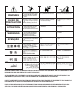
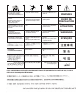
NOTE: The cable contains three control leads. Any
two control leads can be used, provided the two color
used are the same at both ends. The extra lead is a
spare that can be used if one of the other leads
breaks
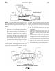
g. Check that the cable boot and both halves of the
strain relief are on the cable. Slip the connector nut
over the copper strands with the thread end out.
Orient gun tube connector so machined flat is on
the same side of the cable as the red and white
control leads. Assemble gun tube connector to
cable by forcing the steel tube of the connector
into the inside diameter of the cable inner tube
until the copper strands are butted against the gun
tube connector shoulder. Keeping the copper
strands against the shoulder, pull the connector
nut over the copper strands, engage the gun tube
c
onnector threads, and tighten in place
. Figure D.2.
NOTE: For best results, insert a .175/.197 inch (4.5-
5.0 mm) diameter rod through the connector and into
core of cable approximately 5.00 inch (127 mm) when
pushing the connector tube into the cable core tube.
To tighten, hold the connector in place while turning
the nut, and remove the rod from the core, The proce-
dure ensures the inner core does not kink while
assembling or tightening.
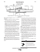
h. Pull the cut-off lead terminals off the trigger
assemble and connect the replacement control
lead terminals.
i. Position the cable boot and strain relief on the
cable so it fits in cable handle cavity and lock the
strain relief in place by pushing the two halves
together.
j. Assemble cable in left side of gun handle.
Assemble trigger into the proper handle cavity and
connect the control leads. Assemble right side of
gun handle and tighten the three screws that hold
the handle together. Refer to Figure D.3.
k. Install gun tube per Gun Tubes and Nozzles
Section.
l. Install and trim liner per Liner Installation Section.
'N 'N"$!'$(' %
'$
'$