
Welder User Manual


POWER MIG 255
OPERATION
B-4 B-4
Return to Section TOC Return to Section TOC Return to Section TOC Return to Section TOC
Return to Master TOC Return to Master TOC Return to Master TOC Return to Master TOC
DESCRIPTION OF CONTROLS
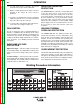
Power ON/OFF Switch — Place the lever in the “ON”
position to energize the POWER MIG 255. When the
power is on, the red LED display lights illuminate.
Voltage Control — This is a continuous control that
gives full range adjustment of power source output volt-
age. It can be adjusted while welding over its 10 to 28
volt range.
Wire Speed Control — This controls the wire feed
speed from 50 to 700 inches per minute (1.2 to
17.8 m/min). The wire speed control can be preset on
the dial to the setting specified on the Procedure Decal
located inside the wire compartment door. Wire speed
is not affected when changes are made in the voltage
control.
WIRE DRIVE ROLL
The drive rolls installed with the POWER MIG each
have two grooves, both for 0.030-0.0035 in.
(0.8-0.9 mm) solid steel electrode. Drive roll size is indi-
cated by the stencilling on the exposed side of the drive
roll. If feeding problems occur, then the drive roll may
be reversed or changed. See Procedure for
Changing Drive Roll in this section. This information
also appears on the Procedure Decal on the door
inside the wire compartment. An additional drive roll set
is provided for 0.045 in. (1.2 mm) solid steel electrode,
packaged standard with each machine.
WIRE SIZE CONVERSION PARTS
The POWER MIG 255 is rated to feed 0.025 through
0.045 in. (0.6 to 1.2 mm) solid or cored electrode sizes.
The drive roll kits and Magnum 250L gun and cable
parts are available to feed different sizes and types of
electrodes. See Accessories section.
FIGURE B.1 — OPERATOR CONTROLS
POWER
POWER MIG 255
WIRE SPEED
ON
OFF
VOLTS
LINCOLN
ELECTRIC