RETURN TO MAIN MENU SAE400 & SAE400 WELD’N AIR DC ARC WELDING POWER SOURCE IM640-A May, 2004 For use with machines having Code Numbers: 10601, 10602, 10884, 10885 Safety Depends on You Lincoln arc welding and cutting equipment is designed and built with safety in mind. However, your overall safety can be increased by proper installation ... and thoughtful operation on your part. DO NOT INSTALL, OPERATE OR REPAIR THIS EQUIPMENT WITHOUT READING THIS MANUAL AND THE SAFETY PRECAUTIONS CONTAINED THROUGHOUT.
i i SAFETY WARNING CALIFORNIA PROPOSITION 65 WARNINGS Diesel engine exhaust and some of its constituents are known to the State of California to cause cancer, birth defects, and other reproductive harm. The Above For Diesel Engines The engine exhaust from this product contains chemicals known to the State of California to cause cancer, birth defects, or other reproductive harm. The Above For Gasoline Engines ARC WELDING CAN BE HAZARDOUS.
ii ii SAFETY ELECTRIC SHOCK can kill. ARC RAYS can burn. 3.a. The electrode and work (or ground) circuits are electrically “hot” when the welder is on. Do not touch these “hot” parts with your bare skin or wet clothing. Wear dry, hole-free gloves to insulate hands. 4.a. Use a shield with the proper filter and cover plates to protect your eyes from sparks and the rays of the arc when welding or observing open arc welding. Headshield and filter lens should conform to ANSI Z87. I standards. 3.b.
iii iii SAFETY WELDING SPARKS can cause fire or explosion. 6.a. Remove fire hazards from the welding area. If this is not possible, cover them to prevent the welding sparks from starting a fire. Remember that welding sparks and hot materials from welding can easily go through small cracks and openings to adjacent areas. Avoid welding near hydraulic lines. Have a fire extinguisher readily available. 6.b.
iv iv SAFETY PRÉCAUTIONS DE SÛRETÉ Pour votre propre protection lire et observer toutes les instructions et les précautions de sûreté specifiques qui parraissent dans ce manuel aussi bien que les précautions de sûreté générales suivantes: Sûreté Pour Soudage A L’Arc 1. Protegez-vous contre la secousse électrique: a. Les circuits à l’électrode et à la piéce sont sous tension quand la machine à souder est en marche.
v SAFETY WARNING Assure that tank and compressor relief valves work properly, and are at correct pressure settings. DO NOT modify or repair air tank. NEVER move compressor with pressure in tank.
vi SAFETY vi
vii vii Thank You for selecting a QUALITY product by Lincoln Electric. We want you to take pride in operating this Lincoln Electric Company product ••• as much pride as we have in bringing this product to you! Please Examine Carton and Equipment For Damage Immediately When this equipment is shipped, title passes to the purchaser upon receipt by the carrier.
viii TABLE OF CONTENTS Page Installation Instructions . . . . . . . . . . . . . . . . . . . . . . . . . . . . . . . . . . . . . . . . . . . . Section A Technical Specifications . . . . . . . . . . . . . . . . . . . . . . . . . . . . . . . . . . . . . . . . . . . . . . . .A-1 Installation Precautions . . . . . . . . . . . . . . . . . . . . . . . . . . . . . . . . . . . . . . . . . . . . . . . . A-2 Location / Ventilation . . . . . . . . . . . . . . . . . . . . . . . . . . . . . . . . . . . . . . . . . . . .
A-1 A-1 INSTALLATION TECHNICAL SPECIFICATIONS - SAE400 & SAE400 WELD’N AIR INPUT - DIESEL ENGINE Make/Model Description Speed (RPM) Displacement Starting System Capacities Perkins 1004.42 Diesel Engine 4 cylinder 71 HP @ 1725 RPM High Idle 1800 Low Idle 1100 Full Load 1725 256 cu. in (4.2 L) 12VDC batteries (2) & Starter Fuel: 22.5 gal. 85.1 L Bore x Stroke Oil: 8.5 Qts. 8.04 L 3.875” x 5.00” Coolant: 3.6 gal. 13.63 L (98.4 mm x 127.
A-2 A-2 INSTALLATION Read this entire installation section before you start installation. SAFETY PRECAUTIONS WARNING Do not attempt to use this equipment until you have thoroughly read all operating and maintenance manuals supplied with your machine. They include important safety precautions, detailed engine starting, operating and maintenance instructions and parts lists. ELECTRIC SHOCK can kill. •Do not touch electrically live parts such as output terminals or internal wiring.
A-3 A-3 INSTALLATION HIGH ALTITUDE OPERATION At higher altitudes, output derating may be necessary. As a rule of thumb, derate the welder output 5% for every 500 meters (1640 ft.) above 1000 meters (3280 ft.). Contact a Perkins Service Representative for any engine adjustments that may be required for high altitude operation. • Only transport this equipment on serviceable vehicles which are rated and designed for such loads.
A-4 A-4 INSTALLATION WARNING • Stop engine while fueling. • Do not smoke when fueling. • Keep sparks and flame away from tank. • Do not leave unattended while fueling. • Wipe up spilled fuel and allow DIESEL FUEL fumes to clear before starting can cause fire. engine. • Do not overfill tank, fuel expansion may cause overflow. DIESEL FUEL ONLY ------------------------------------------------------------------------ 1. Connect the welder output studs to a suitable resistive load bank.
A-5 A-5 INSTALLATION BATTERY ACID can burn eyes and skin. ● Wear gloves and eye protection and be careful when working near battery. ● Follow instructions printed on battery. IMPORTANT: To prevent ELECTRICAL DAMAGE WHEN: a) Installing new batteries. b) Using a booster. Use correct polarity — Negative Ground. To prevent BATTERY BUCKLING, tighten nuts on batteries only until snug. DO NOT OVERTIGHTEN.
B-1 B-1 OPERATION OPERATING INSTRUCTIONS Read and understand this entire section before operating your equipment. SAFETY INSTRUCTIONS WARNING Do not attempt to use this equipment until you have thoroughly read all operating and maintenance manuals supplied with your machine. They include important safety precautions, detailed engine starting, operating and maintenance instructions and parts lists. ELECTRIC SHOCK can kill.
B-2 OPERATION OTHER FEATURES RECOMMENDED APPLICATIONS WELDER The SAE400 or SAE400 WELD’N AIR provides excellent constant current DC welding output for stick (SMAW) welding. The field installed optional CV Adapter (K385-1) provides up to 500 amps at 35 volts of constant voltage output for semiautomatic welding. AUXILIARY POWER The SAE400 or SAE400 WELD’N AIR provides 3 KW of 115/230 VAC output for auxiliary power and emergency standby power.
B-3 B-3 OPERATION ENGINE CONTROLS ENGINE PROTECTION SYSTEM IGNITION SWITCH The engine protection system shuts down the engine under high coolant temperature or low engine oil pressure conditions by allowing the fuel solenoid valve to close. When placed in the “ON” position, this switch energizes the fuel solenoid. When placed in the “OFF” position, the flow of fuel to the injection pump is stopped to shut down the engine.
B-4 OPERATION B-4 How to Set the Controls Circuit Breakers Assume you want a normal soft arc and about 135 amps, using a 5/32” (4.0 mm) electrode: The circuit breakers provide separate overload current protection for each half of the 115 V duplex receptacle. The circuit breakers provide overload current protection in both current carrying wires of the 230 V duplex receptacle. 1. Set the “Job Selector” at the center of the black range. 2. Set the “Current Control” to read 135 amps on the black dial.
B-5 B-5 OPERATION AIR COMPRESSOR (SAE400 WELD’N AIR only) ENGINE OPERATION CAUTION Do not adjust the high idle engine speed (rpm) above the factory setting specification as this will overspeed the air compressor and void it’s warranty. ------------------------------------------------------------------------ STARTING INSTRUCTIONS Cylinder head stud torque must be checked after initial 8 to 10 hours of operation. See compressor operator’s manual for details.
C-1 ACCESSORIES K930-2 Hi-Freq™ - Provides high frequency plus a gas valve for TIG welding. A water valve is available as an option. Requires 115 volt AC input. (Limited to 250A - 60% Duty Cycle). C-1 K2303-1 SHEET METAL KIT- For SAE400 model K1278-5. K802-D Power Plug Kit - Kit includes male plugs for each auxiliary receptacle. K767-1 Trailer - A 4-wheel steerable trailer for in-plant and yard towing(1) with E78-14 load range (B) tubeless tires. Mounts directly to welder base.
D-1 D-1 MAINTENANCE PERIODIC MAINTENANCE WARNING ELECTRIC SHOCK can kill. ● Do not touch electrically live parts such as output terminals or internal wiring ENGINE EXHAUST can kill. ● Use in open, well ventilated areas or vent exhaust outside MOVING PARTS can injure. ● Do not operate with doors open or guards off ● Stop engine before servicing ● Keep away from moving parts ● Remove guards only when necessary and replace when work requiring removal is complete.
D-2 D-2 MAINTENANCE COMMUTATOR AND BRUSH MAINTENANCE WARNING Uncovered rotating equipment can be dangerous. Use care so your hands, hair, clothing or tools do not catch in the rotating parts. Protect yourself from particles that may be thrown out by the rotating armature when stoning the commutator. -----------------------------------------------------------------------The generator brushes are properly adjusted when the welder is shipped. They require no particular attention.
D-3 MAINTENANCE 4. Using a pair of pliers, gently tug on the pull tabs of the pre-filter screen in an alternating pattern to gradually remove the pre-filter screen. 5. Brush off any debris and rinse in diesel fuel. 6. Re-install the pre-filter screen into the upper cavity of the filter header making sure the four pull tabs are pointing up. Putting your fingers on the pull tabs, push down evenly until the lower body of the pre-filter screen contacts the floor of the upper cavity. 7.
D-4 D-4 MAINTENANCE ENGINE AND COMPRESSOR MAINTENANCE COMPONENTS ITEM MAKE Engine Air Filter Donaldson SPARK ARRESTOR WARNING PART NUMBER P181052 • Spark Arrester and Muffler may be hot! • Allow engine to cool before servicing spark arrester! • Do not operate engine while servicing spark arrester! Fan Belt Perkins 2614B550 Compressor Belt (SAE400 WELD’N AIR only) Lincoln Gates S23887 2/A40 Fuel Filter Perkins 26560143 For machines with separate spark arresting units: Service the spark ar
E-1 TROUBLESHOOTING E-1 HOW TO USE TROUBLESHOOTING GUIDE WARNING Service and Repair should only be performed by Lincoln Electric Factory Trained Personnel. Unauthorized repairs performed on this equipment may result in danger to the technician and machine operator and will invalidate your factory warranty. For your safety and to avoid Electrical Shock, please observe all safety notes and precautions detailed throughout this manual.
E-2 E-2 TROUBLESHOOTING Observe all Safety Guidelines detailed throughout this manual PROBLEMS (SYMPTOMS) POSSIBLE CAUSE RECOMMENDED COURSE OF ACTION FUNCTION PROBLEMS Machine fails to hold the “heat” constantly. Rough or dirty commutator. True and clean commutator. Brushes may be worn down to limit of life. Replace brushes. Brush springs may be broken. Replace brush springs.
E-3 E-3 TROUBLESHOOTING Observe all Safety Guidelines detailed throughout this manual PROBLEMS (SYMPTOMS) POSSIBLE CAUSE RECOMMENDED COURSE OF ACTION FUNCTION PROBLEMS Welder runs but fails to generate current. Welding arc is loud and spatters excessively. Generator or exciter brushes may be loose or missing. Be sure that all brushes bear on the commutator and have proper spring tension. Exciter may not be operating. Check exciter output voltage with voltmeter or lamp.
E-4 E-4 TROUBLESHOOTING Observe all Safety Guidelines detailed throughout this manual PROBLEMS (SYMPTOMS) POSSIBLE CAUSE RECOMMENDED COURSE OF ACTION FUNCTION PROBLEMS Welding current too great or too “Current Control” shaft and handle With current control against the minsmall compared to indication on the may have turned slightly in the insu- imum stop, set pointer to within 1/8” dial. lated bushing of the current control of the last scale division.
E-5 E-5 TROUBLESHOOTING Observe all Safety Guidelines detailed throughout this manual PROBLEMS (SYMPTOMS) POSSIBLE CAUSE RECOMMENDED COURSE OF ACTION FUNCTION PROBLEMS No auxiliary power Circuit Breakers open. Check and reset breakers. If breakers keep tripping check connections to auxiliary receptacles. Also make sure load does nor exceed receptacle’s current rating. Faulty connections to auxiliary receptacles. Check connections.
B B 231 220 IDLER SOLENOID U IDLER/ENGINE PROTECTION P.C. BOARD SAE400 & SAE400 WELD’N AIR B 221 B W W G 226 229 B G 5A 232 B 240 B B 241 236 IGNITION SWITCH 5B B G G B S G R G G 86 30 87a 87 85 B 2 CR REED RELAY WARNING: WARNING Turn the engine or input power OFF before maintenance work unless the maintenance work requires it to be running. Keep hands, hair, clothing and tools away from moving parts, and insure all guards or covers are replaced after servicing.
B B 225 220 IDLER/ENGINE PROTECTION P.C. BOARD OIL PRESSURE SWITCH (N.C.) J1 U 1 2 3 J2 4 B 226 SAE400 & SAE400 WELD’N AIR W B W G G R B 5B G B 236 IGNITION SWITCH B G B R STARTING MOTOR S 235 B START B 2 CR WARNING: WARNING Turn the engine or input power OFF before maintenance work unless the maintenance work requires it to be running. Keep hands, hair, clothing and tools away from moving parts, and insure all guards or covers are replaced after servicing.
SAE400 & SAE400 WELD’N AIR B B W 238 G G G CB2 B W B CB4 W W TOROID B 3 4 AC 201 (-) D1 U U 3 W 602B 5 AC 1 B NEG - AC D2 SEE BATTERY WIRING DIAGRAM R R G U R B 1 N 500 F Y 4 W 602 4 5 POLARITY SWITCH P8 6 42 41 3 2 1 600 WELD CURRENT SENSING SWITCH 2CR REACTOR + 42A R B R 4 1 3 G U Y W W G X ELECTRODE M19237 7- 01 W REMOTE SWITCH WIRED THIS WAY ON EARLIER UNITS 602 R R REMOTE CONTROL POTENTIOMETER BOX CONNECT TO BASE RESISTORS TO
SAE400 & SAE400 WELD’N AIR 27.12 24.50 22.14 22.00 28.00 * * 6.00 39.69 = .69 DIA HOLES = .81 DIA HOLES BUT NO FUEL. WATER IN ENGINE, WITH OIL AND CENTER OF GRAVITY 50.13 32.87 43.75 63.06 69.75 * 83.00 81.25 77.00 44.50 8.90 39.38 1-98 M8869-33 .88 8.12 3.00 18.
NOTES SAE400 & SAE400 WELD’N AIR
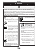
● Keep your head out of fumes. ● Use ventilation or exhaust to ● Turn power off before servicing. ● Do not operate with panel open or guards off. remove fumes from breathing zone. ● Los humos fuera de la zona de res- piración. ● Mantenga la cabeza fuera de los humos. Utilice ventilación o aspiración para gases. ● Gardez la tête à l’écart des fumées. ● Utilisez un ventilateur ou un aspira- ● Desconectar el cable de ali- mentación de poder de la máquina antes de iniciar cualquier servicio.
WARNING Spanish AVISO DE PRECAUCION French ATTENTION German WARNUNG Portuguese ATENÇÃO ● Do not touch electrically live parts or ● Keep flammable materials away. ● Wear eye, ear and body protection. ● Mantenga el material combustible ● Protéjase los ojos, los oídos y el electrode with skin or wet clothing. ● Insulate yourself from work and ground. ● No toque las partes o los electrodos bajo carga con la piel o ropa mojada. ● Aislese del trabajo y de la tierra.
• World's Leader in Welding and Cutting Products • • Sales and Service through Subsidiaries and Distributors Worldwide • Cleveland, Ohio 44117-1199 U.S.A. TEL: 216.481.8100 FAX: 216.486.1751 WEB SITE: www.lincolnelectric.