
Welder User Manual


INPUT CONNECTION
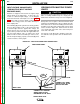
Only a qualified electrician should connect the input
leads to the Power Wave. Connections should be made
in accordance with all local and national electrical codes
and the connection diagram located on the inside of the
reconnect/input access door of the machine. Failure to
do so may result in bodily injury or death.
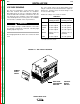
Use a three-phase supply line. A 1.75 inch (45 mm)
diameter access hole for the input supply is located on
the upper left case back next to the input access door.
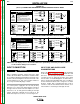
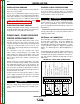
Connect L1, L2, L3 and ground according to the Input
Supply Connection Diagram decal located on the
inside of the input access door, or refer to Figure A.1.
INPUT FUSE AND SUPPLY WIRE
CONSIDERATIONS
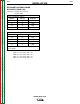
Refer to the Technical Specifications at the beginning
of this Installation section for recommended fuse and
wire sizes. Fuse the input circuit with the recommend-
ed super lag fuse or delay type breakers (also called
“inverse time” or “thermal/magnetic” circuit breakers).
Choose an input and grounding wire size according to
local or national electrical codes. Using fuses or circuit
breakers smaller than recommended may result in
“nuisance” shut-offs from welder inrush currents, even
if the machine is not being used at high currents.
A-5 A-5
INSTALLATION
POWER WAVE 455/R
Return to Section TOC Return to Section TOC Return to Section TOC Return to Section TOC
Return to Master TOC Return to Master TOC Return to Master TOC Return to Master TOC
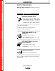
WARNING
NOTE:Turn main input power to the machine OFF before performing connection procedure. Failure to do
so will result in damage to the machine.
FIGURE A.1
(K1761-1) CONNECTION DIAGRAM ON CONNECTION/INPUT ACCESS DOOR
200-208V
220-230V
440-460V
550-575V
200-208V
220-230V
VOLTAGE = 220-230V
220-230V
200-208V
220-230V
440-460V
550-575V
200-208V
U / L1
550-575V
440-460V
inspecting or servicing machine.
Do not operate with covers
removed.
Do not touch electrically live parts.
Only qualified persons should install,
use or service this equipment.
'A'
'A'
VOLTAGE = 440-460V
'A'
S25198
VOLTAGE = 200-208V
THE LINCOLN ELECTRIC CO. CLEVELAND, OHIO U.S.A.
XA
'A'
VOLTAGE = 550-575V
CR1
W / L3
V / L2
440-460V
550-575V
Disconnect input power before
INPUT SUPPLY CONNECTION DIAGRAM
WARNING
CAN KILL
SHOCK
ELECTRIC
(K1761-2) CONNECTION DIAGRAM ON CONNECTION/INPUT ACCESS DOOR
200-208V
220-230V
380-415V
440-460V
200-208V
220-230V
VOLTAGE=220-230V
220-230V
200-208V
220-230V
380-415V
440-460V
200-208V
U / L1
440-460V
380-415V
.
inspecting or servicing machine.
Do not operate with covers
.
removed.
Do not touch electrically live parts.
.
Only qualified persons should install,
use or service this equipment.
.
'A'
'A'
VOLTAGE=380-415V
'A'
S23847
VOLTAGE=200-208V
THE LINCOLN ELECTRIC CO. CLEVELAND, OHIO U.S.A.
A
'A'
VOLTAGE=440-460V
CR1
W / L3
V / L2
380-415V
440-460V
Disconnect input power before
INPUT SUPPLY CONNECTION DIAGRAM
WARNING
ELECTRIC
SHOCK
CAN KILL
ELECTRIC
SHOCK
CAN KILL
WARNING