
Welder User Manual


TROUBLESHOOTING & REPAIR
F-12 F-12
POWER WAVE 455/R
Return to Section TOC Return to Section TOC Return to Section TOC Return to Section TOC
Return to Master TOC Return to Master TOC Return to Master TOC Return to Master TOC
19C
19D
RECONNECT
SWITCHES
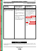
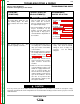
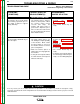
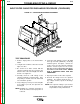
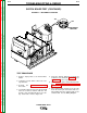
FIGURE F.2 – RECONNECT SWITCHES
SWITCH BOARD TEST (CONTINUED)
TEST PROCEDURE
1. Remove input power to the Power Wave
455/R.
2. Using the 3/8” nut driver, remove the case
top and sides.
3. Perform the Capacitor Discharge
Procedure.
4. Locate label and remove leads 19C and 19D
from the reconnect switches with the 3/8”
wrench. Note lead placement for reassem-
bly. Clear leads. Refer to Figure F.2.
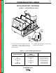
5. Using the Analog ohmmeter, perform the
resistance tests detailed in Table F.1. Refer
to Figure F.3 for the test points.
6. If any test fails replace both switch boards.
See Switch Board Removal and
Replacement.
7. If the switch board resistance tests are OK,
check the molex pin connections and asso-
ciated wiring from the switch boards to the
control board. See the Wiring Diagram.