
Welder User Manual

TROUBLESHOOTING & REPAIR
F-21 F-21
POWER WAVE 455/R
Return to Section TOC Return to Section TOC Return to Section TOC Return to Section TOC
Return to Master TOC Return to Master TOC Return to Master TOC Return to Master TOC
DC BUS
POWER
SUPPLY
PC BOARD
CAPACITOR
C3
CAUTION!
J47
J46
J46
J47
3 4 5 6 7 8
LED
1 2 3 4
1 2
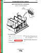
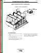
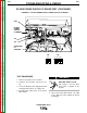
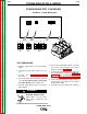
FIGURE F.7 – DC BUS POWER SUPPLY POWER SUPPLY PC BOARD
DC BUS POWER SUPPLY PC BOARD TEST (CONTINUED)
TEST PROCEDURE
1. Remove input power to the machine.
2. Using the 3/8” nut driver, remove the case
top.
3. Locate the DC Bus Power Supply PC Board
and plugs P46 and P47. See Figure F.7.
4. Carefully apply input power to the Power
Wave 455/R.
ELECTRIC SHOCK can kill.
High voltage is present when
input power is applied to the
machine.
5. Turn on the Power Wave 455/R. The LED
on the DC Bus Power Supply PC Board
should light.
WARNING