
Welder User Manual


TROUBLESHOOTING & REPAIR
F-32 F-32
POWER WAVE 455/R
Return to Section TOC Return to Section TOC Return to Section TOC Return to Section TOC
Return to Master TOC Return to Master TOC Return to Master TOC Return to Master TOC
STT CHOPPER BOARD TEST (CONTINUED)
4. Carefully apply input power to the Power
Wave 455/R.
ELECTRIC SHOCK can kill.
High voltage is present when
input power is applied to the
machine.
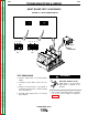
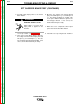
For steps 5 and 6, see Figure F.10.
5. Turn on the Power Wave 455/R. Measure
the voltage from Power Board plug J43 lead
345 pin 7 (+) to lead 346 pin 1 (-). The volt-
age should be approximately 20 VDC. If not
correct, the Power Board may be faulty.
6. Measure the voltage from Control Board
plug J7 lead 4W pin 13 (-) to lead 4R pin 14
(+). The voltage should be 4 – 5 VDC. This
is the pulse width modulation signal to the
STT Chopper Board. If not correct, the
Control Board may be faulty.
7. When the test is completed, remove input
power from the Power Wave 455/R.
8. Install the case top using the 3/8” nut driver.
WARNING