
Welder User Manual


J
60
J48
J40/50
Output Choke
Connection
Fan Relay
Front Horizontal
Divider Panel
Rear Horizontal
Divider Panel
Front Panel Screws
Power
Switch
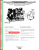
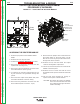
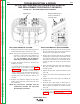
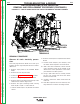
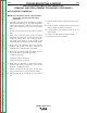
FIGURE F.21 – ACCESSING THE RECTIFIER MODULE
OUTPUT RECTIFIER MODULE REPLACEMENT
PROCEDURE (CONTINUED)
ACCESSING THE RECTIFIER MODULE
1. Remove input power to the POWER WAVE
655/R.
2. Remove the case top and sides.
3. Perform the Capacitor Discharge procedure.
4. Disconnect the J60 Molex connector from the
Input Board. (See Fig. F.21).
5. Disconnect J40 and J50 Molex connectors from
the Switch Boards. (See Fig.F.21).
6. Cut wire ties as necessary and pull the J40, J50
& J60 harnesses and grommets through the
panels.
7. Disconnect the output leads (444 & X3A) from
the bottom terminals of the Fan Relay.
8. Disconnect the J48 Molex connector from the
DC Bus Board (lower connector - 4 pin).
9. Remove the two phillips head screws that hold
the Power Switch to the front panel. Cut the
wire ties as necessary and pull the switch out to
the right side of the machine.
10. Remove the 1/2” bolt that holds the Output
choke to the Negative Output Stud.
11. Loosen (do not remove) the three screws at the
bottom of the front panel.
12. Remove the four screws tha hold the Front
Horizontal Divider panel to the Rear Horizontal
panel.
13. Tilt the front panel forward far enough to
expose all four pairs of diode modules.
CAUTION: Be careful not to stress or damage
the Current Transformer leads that
are routed past the right side of the
rectifier assembly.
TROUBLESHOOTING & REPAIR
F-60 F-60
POWER WAVE 655/R
Return to Section TOC Return to Section TOC Return to Section TOC Return to Section TOC
Return to Master TOC Return to Master TOC Return to Master TOC Return to Master TOC