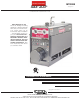
RETURN TO MAIN MENU IM10088 SAE-300® January, 2011 For Machines with Code Numbers 11645 Safety Depends on You Lincoln arc welding and cutting equipment is designed and built with safety in mind. However, your overall safety can be increased by proper installation ... and thoughtful operation on your part. DO NOT INSTALL, OPERATE OR REPAIR THIS EQUIPMENT WITHOUT READING THIS MANUAL AND THE SAFETY PRECAUTIONS CONTAINED THROUGHOUT. And, most importantly, think before you act and be careful.
i i SAFETY WARNING CALIFORNIA PROPOSITION 65 WARNINGS Diesel engine exhaust and some of its constituents are known to the State of California to cause cancer, birth defects, and other reproductive harm. The Above For Diesel Engines The engine exhaust from this product contains chemicals known to the State of California to cause cancer, birth defects, or other reproductive harm. The Above For Gasoline Engines ARC WELDING CAN bE hAzARDOuS.
ii ii SAFETY ELECTRIC ShOCK can kill. 3.a. The electrode and work (or ground) circuits are electrically “hot” when the welder is on. Do not touch these “hot” parts with your bare skin or wet clothing. Wear dry, hole-free gloves to insulate hands. 3.b. Insulate yourself from work and ground using dry insulation. Make certain the insulation is large enough to cover your full area of physical contact with work and ground.
iii iii SAFETY WELDING and CuTTING SPARKS can cause fire or explosion. 6.a. Remove fire hazards from the welding area. If this is not possible, cover them to prevent the welding sparks from starting a fire. Remember that welding sparks and hot materials from welding can easily go through small cracks and openings to adjacent areas. Avoid welding near hydraulic lines. Have a fire extinguisher readily available. 6.b.
iv SAFETY PRÉCAuTIONS DE SÛRETÉ Pour votre propre protection lire et observer toutes les instructions et les précautions de sûreté specifiques qui parraissent dans ce manuel aussi bien que les précautions de sûreté générales suivantes: Sûreté Pour Soudage A L’Arc 1. Protegez-vous contre la secousse électrique: a. Les circuits à l’électrode et à la piéce sont sous tension quand la machine à souder est en marche.
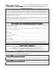
v v Thank You for selecting a QuALITY product by Lincoln Electric. We want you to take pride in operating this Lincoln Electric Company product ••• as much pride as we have in bringing this product to you! CuSTOMER ASSISTANCE POLICY The business of The Lincoln Electric Company is manufacturing and selling high quality welding equipment, consumables, and cutting equipment. Our challenge is to meet the needs of our customers and to exceed their expectations.
vi vi TAbLE OF CONTENTS Page Installation .......................................................................................................Section A Technical Specifications ........................................................................................A-1 General Description ...............................................................................................A-2 Design Features ....................................................................................................
A-1 A-1 INSTALLATION TEChNICAL SPECIFICATIONS - SAE-300® INPuT - DIESEL ENGINE Make/Model Perkins 404D-22 EPA Tier 4 interim Compliant Description Speed (RPM) 4 Cylinder 4 Cycle Naturally Aspirated High Idle 1800 Water-Cooled Low Idle 1400 Diesel Engine Full Load 1725 Cast Iron Cylinder, Block/Crankcase Displacement 135 cu. in (2.2 ltrs) bore x Stroke Starting System Dry Capacities 12VDC battery (Group 24, 650 cold crank amps) 2.0 KW Starter Fuel: 16 gal. 60.6 L. 3.3” x 3.
A-2 INSTALLATION GENERAL DESCRIPTION The SAE-300® is a heavy duty, engine driven, DC arc welding power source, capable of providing constant current output for stick welding or DC TIG welding. This welder is wound with all copper coils, rated at 300 amps/32 Volts, and provides other Classic® features such as improved door latches and stainless hinges.
A-3 A-3 INSTALLATION PRE-OPERATION INSTALLATION CAuTION DO NOT MOuNT OVER COMbuSTIbLE SuRFACES. WARNING Do not attempt to use this equipment until you have thoroughly read the engine manufacturer’s manual supplied with your welder. It includes important safety precautions, detailed engine starting, operating and maintenance instructions, and parts lists. -----------------------------------------------------------------------ELECTRIC ShOCK can kill.
A-4 A-4 INSTALLATION 2. Proper support of, and attachment to, the base of the welding equipment so there will be no undue stress to the framework. PRE-OPERATION SERVICE 3. Proper placement of the equipment on the trailer to ensure stability side to side and front to back when being moved and when standing by itself while being operated or serviced. READ the engine operating and maintenance instructions supplied with this machine.
A-5 INSTALLATION bATTERY ChARGING WARNING GASES FROM bATTERY can explode. • Keep sparks, flame and cigarettes away. bATTERY ACID can burn eyes and skin. • Wear gloves and eye protection and be careful when boosting, charging or working near battery. To prevent ExPLOSION when: a) Installing a new battery - disconnect thenegative cable from the old battery first and connect the negative cable to the new battery last.
b-1 b-1 OPERATION ENGINE OPERATION 7. WARNING Do not attempt to use this equipment until you have thoroughly read the engine manufacturer’s manual supplied with your welder. It includes important safety precautions, detailed engine starting, operating and maintenance instructions, and parts lists. -----------------------------------------------------------------------ELECTRIC ShOCK can kill. • Do not touch electrically live parts or electrode with skin or wet clothing.
b-2 b-2 OPERATION ENGINE bREAK-IN DuTY CYCLE Lincoln Electric selects high quality, heavy-duty industrial engines for the portable welding machines we offer. While it is normal to see a small amount of crankcase oil consumption during initial operation, excessive oil use, wet stacking (oil or tar like substance at the exhaust port), or excessive smoke is not normal.
b-3 b-3 OPERATION GAS-ShIELDED FLux-CORED WELDING (WITh A K623-1 WIRE FEED MODuLE INSTALLED) Start by setting the Wire (CV) / Stick (CC) toggle switch to the Wire (CV) position. Then set the left-side Coarse Current control dial to 150. Now move the Voltage Adjustment dial to the desired voltage. Move the Coarse Current control to the left for a softer arc and to the right for a crisper arc. 1. In the “High” position, the idler solenoid deactivates, and the engine goes to high idle speed.
C-1 ACCESSORIES OPTIONAL FEATuRES C-1 TIG OPTIONS (Field Installed) GENERAL OPTIONS WARNING Pipe Thawing with an arc welder can cause fire, explosion, damage to electric wiring or to the arc welder if done improperly. The use of an arc welder for pipe thawing is not approved by the CSA, nor is it recommended or supported by Lincoln Electric. -----------------------------------------------------------------------Power Plug Kit K802D A power plug kit for the auxiliary power receptacles is available.
C-2 ACCESSORIES C-2 WIRE FEEDER OPTIONS Magnum Spool Gun K487-25 Wire Feed Module K623-1 Provides constant voltage (CV) output with improved arc stability for Innershield welding. Excellent for MIG welding. Recommended wire feeders are the LN-7, LN-23P and LN-25. Hand held semiautomatic wire feeder requires SG Control Module. 25 ft. length. Remote Control Kit K2464-1 (Stick & Wire) For Classic® and Pipeliner® machines that have the wire feed module.
D-1 D-1 MAINTENANCE SAFETY PRECAuTIONS COOLING SYSTEM WARNING have qualified personnel do the maintenance work. Turn the engine off before working inside the machine. In some cases, it may be necessary to remove safety guards to perform required maintenance. Remove guards only when necessary and replace them when the maintenance requiring their removal is complete. Always use the greatest care when working near moving parts. Do not put your hands near the engine cooling blower fan.
D-2 D-2 MAINTENANCE Replace brushes when they wear within 1/4” of the pigtail. A complete set of replacement brushes should be kept on hand. Lincoln brushes have a curved face to fit the commutator. Have an experienced maintenance man seat these brushes by lightly stoning the commutator as the armature rotates at full speed until contact is made across the full face of the brushes. After stoning, blow out the dust with low pressure air. To seat slip ring brushes, position the brushes in place.
D-3 MAINTENANCE SAE-300® D-3
D-4 GFCI TESTING PROCEDuRE MAINTENANCE AND RESETTING The GFCI should be properly tested at least once every month or whenever it is tripped. To properly test and reset the GFCI : • If the GFCI has tripped, first carefully remove any load and check it for damage. • If the equipment has been shut down, it must be restarted.
E-1 TROubLEShOOTING E-1 hOW TO uSE TROubLEShOOTING GuIDE WARNING Service and Repair should only be performed by Lincoln Electric Factory Trained Personnel. Unauthorized repairs performed on this equipment may result in danger to the technician and machine operator and will invalidate your factory warranty. For your safety and to avoid Electrical Shock, please observe all safety notes and precautions detailed throughout this manual.
E-2 E-2 TROubLEShOOTING Observe all Safety Guidelines detailed throughout this manual PRObLEMS (SYMPTOMS) Machine fails to hold the output (heat) consistently. POSSIbLE CAuSE RECOMMENDED COuRSE OF ACTION 1. Rough or dirty commutator. 2. Brushes may be worn down to Limit. 3. Field circuit may have variable resistance connection or intermittent open circuit due to If all recommended possible areas of loose connection or broken misadjustment have been checked and the problem persists, Contact wire.
TROubLEShOOTING Observe all Safety Guidelines detailed throughout this manual PRObLEMS (SYMPTOMS) Welder starts but fails to generate current. POSSIbLE AREAS OF MISADJuSTMENTS(S) 1. Generator or exciter brushes may be loose or missing. 2. Exciter may not be operating. 3. Field circuit of generator or exciter may be open. 4. 5. Welding arc is loud and spatters excessively.
E-3 E-3 TROubLEShOOTING ELECTRONIC IDLER TROubLEShOOTING GuIDE With Idler Control Switch in the Auto Position, Engine Will Not Return to Low Idle in Approximately 15 Seconds After Welding and Auxiliary Loads are Removed Set Idler Control Switch to the Auto Position Check for Continuity through Idler Control Switch Open Closed Measure DC Voltage on Idler Solenoid Coil Replace Idler Control Switch 0 VDC 12 VDC Check Continuity of Reed Switch in Weld Circuit Check for Jamming of the Idler Solenoid
E-4 TROubLEShOOTING E-4 ELECTRONIC IDLER TROubLEShOOTING GuIDE With Idler Control Switch in the AuTO Position, Engine Will Not Pick up Speed When: The Arc is Struck The Auxiliary Power Load is Turned ON Reed Switch in Weld Circuit Defective -- Will Not Close Power Load Too Small Try Load Above 150 Watts To Check: Short the Red Lead on P.C. Board to Welder Frame. Engine Does Not Pick up Speed 1. Check for Jamming of the Idler Solenoid Mechanism, or broken return spring. Engine Picks up Speed 1.
E-5 E-5 TROubLEShOOTING Observe all Safety Guidelines detailed throughout this manual PRObLEMS (SYMPTOMS) Engine does not start. Engine does not turn over. POSSIbLE CAuSE 1. Lack of fuel. 2. Air mixed in the fuel system. 3. Clogged fuel filter. 4. Irregular and faulty fuel supply (Injector pump trouble). 5. Glow plug not heated. 6. Clogged air cleaner. 7. No compression. 8. Engine protection light is ON. 1. Faulty Ignition switch and or Injector pump solenoid. 2.
E-6 E-6 TROubLEShOOTING Observe all Safety Guidelines detailed throughout this manual PRObLEMS (SYMPTOMS) POSSIbLE CAuSE RECOMMENDED COuRSE OF ACTION Engine stops during operation and 1. Overheat of the Engine. the Engine Protection light does turn on. Lack of Coolant Supply coolant. Inspect leakage and correct. Loose or slipping fan belt Remove oil, dust, etc. and tighten. Damaged fan belt. Replace. Clogged radiator Flush the radiator. Clogged radiator fin. Clean.
E-7 E-7 TROubLEShOOTING Observe all Safety Guidelines detailed throughout this manual PRObLEMS (SYMPTOMS) White or Blue Smoke. POSSIbLE CAuSE 3. Excess engine oil. Too low viscosity of the engine oil. Faulty injection timing. Dark Grey Smoke. 1. 2. 3. 4. 5. Unsuitable fuel. Excess injection. Faulty function of the engine. Overloading. Clogged air cleaner. Faulty Charging. 1. 2. 3. 4. Loose fan belt. Faulty wiring. Faulty battery. Worn out alternator brush. Starter Motor does not run. 1. 2. 3.
NOTE: This diagram is for reference only. It may not be accurate for all machines covered by this manual. The specific diagram for a particular code is pasted inside the machine on one of the enclosure panels. If the diagram is illegible, write to the Service Department for a replacement. Give the equipment code number.
SAE-300® 4.00 26.63 41.66 23.00 57.80 4.00 N.B. N.A. 8.70 NOTES: N.A. CENTER OF GRAVITY WITH OIL AND WATER IN ENGINE, BUT NO FUEL. N.B. Ø.56 TRAILER MOUNTING HOLES. 3.35 .56 SKID MOUNTING HOLE 13.50 CONTROL PANEL 65.00 .56 SKID MOUNTING HOLE 37.12 45.50 20.62 18.50 24.00 00.42 26.02 05.81 05.54 21.73 DIKS 65. ELOH GNITNUOM .A.N 00.56 66.14 00.32 .B.N 00.4 08.75 36.62 53.3 05.31 DIKS 65. ELOH GNITNUOM LENAP LORTNOC 00.4 :SETON .
l Do not touch electrically live parts or WARNING Spanish AVISO DE PRECAuCION French ATTENTION German WARNuNG Portuguese ATENÇÃO l Keep flammable materials away. l Wear eye, ear and body protection. l Mantenga el material combustible l Protéjase los ojos, los oídos y el electrode with skin or wet clothing. l Insulate yourself from work and ground. l No toque las partes o los electrodos bajo carga con la piel o ropa mojada. l Aislese del trabajo y de la tierra.
l Keep your head out of fumes. l Use ventilation or exhaust to l Turn power off before servicing. l Do not operate with panel open or guards off. remove fumes from breathing zone. l Los humos fuera de la zona de res- piración. l Mantenga la cabeza fuera de los humos. Utilice ventilación o aspiración para gases. l Gardez la tête à l’écart des fumées. l Utilisez un ventilateur ou un aspira- l Desconectar el cable de ali- mentación de poder de la máquina antes de iniciar cualquier servicio.
• World's Leader in Welding and Cutting Products • • Sales and Service through Subsidiaries and Distributors Worldwide • Cleveland, Ohio 44117-1199 U.S.A. TEL: 216.481.8100 FAX: 216.486.1751 WEB SITE: www.lincolnelectric.