RETURN TO MAIN MENU IM10048 VANTAGE 400 (AU) ® For use with machines having Code Numbers: March, 2010 11687 Safety Depends on You Lincoln arc welding and cutting equipment is designed and built with safety in mind. However, your overall safety can be increased by proper installation ... and thoughtful operation on your part. DO NOT INSTALL, OPERATE OR REPAIR THIS EQUIPMENT WITHOUT READING THIS MANUAL AND THE SAFETY PRECAUTIONS CONTAINED THROUGHOUT.
i i SAFETY WARNING CALIFORNIA PROPOSITION 65 WARNINGS Diesel engine exhaust and some of its constituents are known to the State of California to cause cancer, birth defects, and other reproductive harm. The Above For Diesel Engines The engine exhaust from this product contains chemicals known to the State of California to cause cancer, birth defects, or other reproductive harm. The Above For Gasoline Engines ARC WELDING CAN BE HAZARDOUS.
ii ii SAFETY ELECTRIC SHOCK can kill. 3.a. The electrode and work (or ground) circuits are electrically “hot” when the welder is on. Do not touch these “hot” parts with your bare skin or wet clothing. Wear dry, hole-free gloves to insulate hands. 3.b. Insulate yourself from work and ground using dry insulation. Make certain the insulation is large enough to cover your full area of physical contact with work and ground.
iii iii SAFETY WELDING and CUTTING SPARKS can cause fire or explosion. 6.a. Remove fire hazards from the welding area. If this is not possible, cover them to prevent the welding sparks from starting a fire. Remember that welding sparks and hot materials from welding can easily go through small cracks and openings to adjacent areas. Avoid welding near hydraulic lines. Have a fire extinguisher readily available. 6.b.
iv iv SAFETY PRÉCAUTIONS DE SÛRETÉ Pour votre propre protection lire et observer toutes les instructions et les précautions de sûreté specifiques qui parraissent dans ce manuel aussi bien que les précautions de sûreté générales suivantes: Sûreté Pour Soudage A L’Arc 1. Protegez-vous contre la secousse électrique: a. Les circuits à l’électrode et à la piéce sont sous tension quand la machine à souder est en marche.
v v SAFETY Electromagnetic Compatibility (EMC) Conformance Products displaying the CE mark are in conformity with European Community Council Directive of 3 May 1989 on the approximation of the laws of the Member States relating to electromagnetic compatibility (89/336/EEC). It was manufactured in conformity with a national standard that implements a harmonized standard: EN 60974-10 Electromagnetic Compatibility (EMC) Product Standard for Arc Welding Equipment.
vi vi SAFETY Electromagnetic Compatibility (EMC) The size of the surrounding area to be considered will depend on the structure of the building and other activities that are taking place. The surrounding area may extend beyond the boundaries of the premises. Methods of Reducing Emissions Mains Supply Welding equipment should be connected to the mains supply according to the manufacturer’s recommendations.
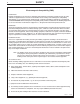
vii vii Thank You for selecting a QUALITY product by Lincoln Electric. We want you to take pride in operating this Lincoln Electric Company product ••• as much pride as we have in bringing this product to you! CUSTOMER ASSISTANCE POLICY The business of The Lincoln Electric Company is manufacturing and selling high quality welding equipment, consumables, and cutting equipment. Our challenge is to meet the needs of our customers and to exceed their expectations.
viii viii TABLE OF CONTENTS Page Installation.......................................................................................................................Section A Technical Specifications ................................................................................................A-1,A-2 Safety Precautions ........................................................................................................A-3 VRD (Voltage Reduction Device) .................................................
ix TABLE OF CONTENTS Maintenance......................................................................................................Section D Safety Precautions ................................................................................................D-1 Routine Maintenance ............................................................................................D-1 Engine Service Items.............................................................................................
A-1 A-1 INSTALLATION TECHNICAL SPECIFICATIONS - VANTAGE® 400 (AU) (K32038-1) INPUT - DIESEL ENGINE Make/Model Code No. Description Speed (RPM) Displacement cu. in. (ltrs.) Starting System Capacities 12VDC Battery 4 cylinder 135.6(2.2) 27.6 HP High Idle 1565 & starter Oil: 1500 RPM Bore x Stroke (Group 34; 650 8.45Qts. (8.0L) Fuel: 20 gal. Perkins 404D-22 naturally aspirated Full Load 1500 cold crank amps) (75.7 L) water cooled 3.43” X 3.
A-2 A-2 INSTALLATION MACHINE SPECIFICATIONS Receptacles 400V (3 Ph) x 1 230V (1 Ph) x 2 14 Pin Connector 6 Pin Connector Residual Current Device (RCD) 4-pole, 40Amp (30mA trip current) Circuit Breakers (Thermal/Magnetic) 3 Phase, 20 Amp x 1 1 phase, 15 Amp x 2 Other Circuit Breakers (5) 10A for Engine Battery Charging Circuit 10A for Wire Feeder Power Center-Tapped to ground.
A-3 A-3 INSTALLATION SAFETY PRECAUTIONS FIGURE A.1 WARNING (VRD)-VOLTAGE REDUCTION DEVICE SWITCH IS LOCATED IN THIS AREA. Do not attempt to use this equipment until you have thoroughly read the engine manufacturer’s manual supplied with your welder. It includes important safety precautions, detailed engine starting, operating and maintenance instructions, and parts lists. -----------------------------------------------------------------------ELECTRIC SHOCK can kill.
A-4 WARNING • Lift only with equipment of adequate lifting capacity. • Be sure machine is stable when lifting. • Do not lift this machine using lift bail if it is equipped with a heavy accessory such as trailer or gas cylinder. FALLING EQUIPMENT can cause injury. A-4 INSTALLATION • Do not lift machine if lift bail is damaged. 1. Design capacity of trailer vs. weight of Lincoln equipment and likely additional attachments. 2.
A-5 A-5 INSTALLATION OIL MUFFLER OUTLET PIPE The VANTAGE® 400 (AU) is shipped with the engine crankcase filled with high quality SAE 10W-30 Oil that meets classification CG4 or CH-4 for diesel engines. Check the oil level before starting the engine. If it is not up to the full mark on the dip stick, add oil as required. Check the oil level every four hours of running time during the first 50 running hours. Refer to the engine Operator’s Manual for specific oil recommendations and break-in information.
A-6 A-6 INSTALLATION WELDING OUTPUT CABLES ELECTRICAL CONNECTIONS MACHINE GROUNDING Because this portable engine driven welder creates its own power, it is not necessary to connect its frame to an earth ground, unless the machine is connected to premises wiring (home, shop, etc.) To prevent dangerous electric shock, other equipment to which this engine driven welder supplies power must: With the engine off connect the electrode and work cables to the output studs.
A-7 INSTALLATION A-7 AUXILIARY POWER CONNECTION OF LINCOLN ELECTRIC WIRE FEEDERS The auxiliary power capacity is 14,000 watts Peak, 13,200 Watts Continuous of 50 Hz, three phase power. The auxiliary power capacity rating in watts is equivalent to volt-amperes at unity power factor. The max permissible current of the 400 VAC output is 22 amps. Output voltage is within ± 10% at all loads up to the rated capacity.
A-8 INSTALLATION WARNING Connection of the LN-25 to the VANTAGE® 400 (AU) Shut off welder before making any electrical connections. -----------------------------------------------------------------------The LN-25 with or without an internal contactor may be used with the VANTAGE® 400 (AU). See the appropriate connection diagram in Section F. NOTE: The LN-25 (K431) Remote Control Module and (K432) Remote Cable are not recommended for use with the VANTAGE® 400 (AU). 1. Shut the welder off. 2.
B-1 B-1 OPERATION SAFETY PRECAUTIONS WARNING Do not attempt to use this equipment until you have thoroughly read the engine manufacturer’s manual supplied with your welder. It includes important safety precautions, detailed engine starting, operating and maintenance instructions, and parts lists. -----------------------------------------------------------------------ELECTRIC SHOCK can kill. • Do not touch electrically live parts or electrode with skin or wet clothing.
B-2 B-2 OPERATION FIGURE B.1 1 11 2 9 3 10 4 14 13 15 12 7 17 8 16 22 20 21 24 18 23 19 5 6 WELDING CONTROLS (Figure B.1) 1. OUTPUT CONTROL- The OUTPUT dial is used to preset the output voltage or current as displayed on the digital meters for the five welding modes.
B-3 B-3 OPERATION 4. ARC CONTROL- The ARC CONTROL dial is active in the CV-WIRE, CC-STICK and DOWNHILL PIPE modes, and has different functions in these modes. This control is not active in the TIG and ARC GOUGING mode. CC-STICK mode: In this mode, the ARC CONTROL dial sets the short circuit current (arc-force) during stick welding to adjust for a soft or crisp arc.
B-4 OPERATION B-4 18. ENGINE PROTECTION LIGHT- A warning indi- ENGINE CONTROLS: 12. RUN/STOP SWITCH - RUN position energizes the engine prior to starting. STOP position stops the engine. The oil pressure interlock switch prevents battery drain if the switch is left in the RUN position and the engine is not operating. 13. GLOW PLUG PUSH BUTTON • When pushed activates the glow plugs. Glow plug should not be activated for more than 20 seconds continuously. 14.
B-5 OPERATION NOTE: If the unit fails to start turn Run/Stop switch to off and repeat step 3 through step 7 after waiting 30 seconds. CAUTION • Do not allow the starter motor to run continuously for more than 20 seconds. • Do not push the START button while the engine is running because this can damage the ring gear and/or the starter motor. • If the Engine Protection or Battery Charging Lights do “not” turn off shortly after starting the engine shut off the engine immediately and determine the cause.
B-6 B-6 OPERATION The OUTPUT CONTROL dial adjusts the full output range for pipe welding. The ARC CONTROL dial sets the short circuit current (arc-force) during stick welding to adjust for a soft or more forceful digging arc (crisp). Increasing the number from -10(soft) to +10(crisp) increases the short circuit current which results in a more forceful digging arc. Typically a forceful digging arc is preferred for root and hot passes.
B-7 B-7 OPERATION This will keep the "Solid State" contactor open and provide a "cold" electrode until the Amptrol or Arc Start Switch is pressed. When using the TIG Module, the OUTPUT CONTROL on the VANTAGE® 400 (AU) is used to set the maximum range of the CURRENT CONTROL on the TIG Module or an Amptrol if connected to the TIG Module. NOTE: The TIG process is to receive a low voltage welding process. There is no difference in operation with the VRD “On” or “Off” for this mode.
C-1 ACCESSORIES FIELD INSTALLED OPTIONS / ACCESSORIES K903-1 SPARK ARRESTOR - Includes a heavy gage steel, approved spark arrestor, clamp and adapter for mounting to the muffler exhaust pipe. K704 ACCESSORY SET - Includes 35 ft. (10m) of electrode cable and 30 ft. (9.1m) of work cable, headshield, work clamp electrode holder. Cables are rated at 400 amps, 100% duty cycle. K857 25 ft (7.6m) or K857-1 100 ft. (30.
D-1 MAINTENANCE SAFETY PRECAUTIONS Read the Safety Precautions in the front of this manual and in the Engine Owner’s Manual before working on this machine. WARNING • Have qualified personnel do all maintenance and troubleshooting work. • Turn the engine off before working inside the machine or servicing the engine. • Remove guards only when necessary to perform maintenance and replace them when the maintenance requiring their removal is complete.
D-2 D-2 MAINTENANCE ENGINE OIL CHANGE OIL FILTER CHANGE Drain the engine oil while the engine is warm to assure rapid and complete draining. It is recommended that each time the oil is changed the oil filter be changed as well. • Drain the oil. • Be sure the unit is off. Disconnect the negative battery cable to ensure safety. • Locate oil drain hose and valve in bottom of base and pull through the hole in the battery access panel on the welder.
D-3 D-3 MAINTENANCE Service Instructions Single- and Two-Stage Engine Air Cleaners Inspect the New Filter for Damage Remove the Filter Rotate the filter while pulling straight out. Unfasten or unlatch the service cover. Because the filter fits tightly over the outlet tube to create the critical seal, there will be some initial resistance, similar to breaking the seal on a jar. Gently move the end of the filter back and forth to break the seal then rotate while pulling straight out.
D-4 D-4 MAINTENANCE FUEL COOLING SYSTEM DIESEL FUEL ONLY-Low sulphur fuel or ultra low sulphur fuel in U.S.A. and Canada. WARNING HOT COOLANT can burn skin. • Do not remove cap if radiator is hot. -----------------------------------------------------------------------Check the coolant level by observing the level in the radiator and recovery bottle. Add 50/50 antifreeze / water solution if the level is close to or below the "LOW" mark. do not fill above the "FULL" mark.
D-5 CLEANING THE BATTERY FUEL FILTER 1. Check the fuel filter and fuel pre-filter for water accumulation or sediment. 2. Replace the fuel filter if it is found with excessive water accumulation or sediment. Empty fuel pre-filter. OVERSPEED IS HAZARDOUS The maximum allowable high idle speed for this machine is 1890 RPM, no load. Do NOT tamper with governor components or setting or make any other adjustments to increase the maximum speed.
D-6 MAINTENANCE WELDER / GENERATOR MAINTENANCE STORAGE: Store in clean, dry protected areas. CLEANING: Blow out the generator and controls periodically with low pressure air. Do this at least once a week in particularly dirty areas. BRUSH REMOVAL AND REPLACEMENT: It’s normal for the brushes and slip rings to wear and darken slightly. Inspect the brushes when a generator overhaul is necessary. CAUTION • Do not attempt to polish slip rings while the engine is running.
E-1 TROUBLESHOOTING E-1 HOW TO USE TROUBLESHOOTING GUIDE WARNING Service and Repair should only be performed by Lincoln Electric Factory Trained Personnel. Unauthorized repairs performed on this equipment may result in danger to the technician and machine operator and will invalidate your factory warranty. For your safety and to avoid Electrical Shock, please observe all safety notes and precautions detailed throughout this manual.
E-2 E-2 TROUBLESHOOTING Observe all Safety Guidelines detailed throughout this manual PROBLEMS (SYMPTOMS) POSSIBLE CAUSE RECOMMENDED COURSE OF ACTION Major Physical or Electrical Damage 1. Contact your local Lincoln is Evident. Authorized Field Service Facility. Engine will not "crank". 1. Battery is low, Charge Battery. 2. Loose battery cable connections. Inspect, clean and tighten terminals. 3. Faulty engine starter motor. Contact authorized local Engine Service Shop.
E-3 E-3 TROUBLESHOOTING Observe all Safety Guidelines detailed throughout this manual PROBLEMS (SYMPTOMS) POSSIBLE CAUSE RECOMMENDED COURSE OF ACTION Engine shuts down while under a 1. High radiator coolant temperaload. ture. Reduce load if it is exceeding machine rating. Add coolant to system if low. Clean fins on radiator if dirty. Tighten fan belt if loose. Remove objects blocking or close to intake openings on both sides of base and exhaust end (case back). Engine runs rough. 1.
E-4 E-4 TROUBLESHOOTING Observe all Safety Guidelines detailed throughout this manual PROBLEMS (SYMPTOMS) POSSIBLE CAUSE Engine will not go to high idle when using auxiliary power. 1. Auxiliary power load is less than 100 watts. Idler may not respond with less than a 100 watt load. Set idler to "High". 2. Faulty PC board.(Control or Idler). Engine will not go to high idle under weld or auxiliary loading. 1. Faulty idler solenoid. Check for bent linkage or broken spring. 2. Faulty PC board.
E-5 E-5 TROUBLESHOOTING Observe all Safety Guidelines detailed throughout this manual PROBLEMS (SYMPTOMS) POSSIBLE CAUSE No welding power output. 1. Poor work lead connection to work. Make sure work clamp is tightly connected to clean base metal. 2. "Weld Terminals" switch in wrong position. Place switch in "Weld Terminals On" position when welding without control cable. 3. Faulty PC board or welder alternator. Welder has output but no control. 1.
E-6 E-6 TROUBLESHOOTING Observe all Safety Guidelines detailed throughout this manual PROBLEMS (SYMPTOMS) POSSIBLE CAUSE RECOMMENDED COURSE OF ACTION The welding arc is “cold.” The weld- 1. Make sure the MODE selector ing arc is not stable or is not satis- switch is in the correct position for factory. the engine runs normally. the process being used. (For examThe auxiliary power is normal. ple, CV-WIRE, PIPE, CC-STICK.) 2. Make sure the electrode (wire, gas, voltage, current etc.
F-1 DIAGRAMS VANTAGE® 400 (AU) F-1
F-2 DIAGRAMS VANTAGE® 400 (AU) F-2
F-3 DIAGRAMS VANTAGE® 400 (AU) F-3
F-4 DIAGRAMS VANTAGE® 400 (AU) F-4
NOTE: This diagram is for reference only. It may not be accurate for all machines covered by this manual. The specific diagram for a particular code is included with the machine. If the diagram is illegible, write to the Service Department for a replacement. Give the equipment code number.
25.82 655.8 1.78 45.1 VANTAGE® 400 (AU) 24.00 609.6 6.03 153.25 5.75 146.0 1.27 32.3 35.94 913.0 39.81 16.25 412.8 N.A. CENTER OF GRAVITY WITH OIL IN ENGINE, COOLANT IN RADIATOR, AND EMPTY FUEL TANK. 27.00 685.8 20.60 523.3 28.13 714.5 28.95 735.3 36.06 915.9 60.00 1524.0 55.50 1409.7 N.A. A 46.47 1180.36 2.25 57.
NOTES VANTAGE® 400 (AU)
NOTES VANTAGE® 400 (AU)
● Do not touch electrically live parts or WARNING Spanish AVISO DE PRECAUCION French ATTENTION German WARNUNG Portuguese ATENÇÃO ● Keep flammable materials away. ● Wear eye, ear and body protection. ● Mantenga el material combustible ● Protéjase los ojos, los oídos y el electrode with skin or wet clothing. ● Insulate yourself from work and ground. ● No toque las partes o los electrodos bajo carga con la piel o ropa mojada. ● Aislese del trabajo y de la tierra.
● Keep your head out of fumes. ● Use ventilation or exhaust to ● Turn power off before servicing. ● Do not operate with panel open or guards off. remove fumes from breathing zone. ● Los humos fuera de la zona de res- piración. ● Mantenga la cabeza fuera de los humos. Utilice ventilación o aspiración para gases. ● Gardez la tête à l’écart des fumées. ● Utilisez un ventilateur ou un aspira- ● Desconectar el cable de ali- mentación de poder de la máquina antes de iniciar cualquier servicio.
• World's Leader in Welding and Cutting Products • • Sales and Service through Subsidiaries and Distributors Worldwide • Cleveland, Ohio 44117-1199 U.S.A. TEL: 216.481.8100 FAX: 216.486.1751 WEB SITE: www.lincolnelectric.