RETURN TO MAIN MENU IM649 Wave DesignerTM Safety Depends on You Lincoln arc welding and cutting equipment is designed and built with safety in mind. However, your overall safety can be increased by proper installation ... and thoughtful operation on your part. DO NOT INSTALL, OPERATE OR REPAIR THIS EQUIPMENT WITHOUT READING THIS MANUAL AND THE SAFETY PRECAUTIONS CONTAINED THROUGHOUT. And, most importantly, think before you act and be careful. May, 1999 Wave Designer Pro Off Line - pulse.
i i TABLE OF CONTENTS Page License Information ..................................................................................................... ii Introduction .................................................................................................... Section 1 1.1 Product Overview .......................................................................................... 1-1 1.2 User Responsibility ....................................................................................... 1-1 1.
ii LICENSE INFORMATION ii By clicking the acceptance button or installing the software, you are consenting to be bound by and are becoming a party to this agreement. If you do not agree to all of the terms of this agreement, click the button that indicates you do not accept the terms and do not install the software. (If applicable, you may return the product to the place of purchase for a full refund.
iii LICENSE INFORMATION iii JAVA RUNTIME ENVIRONMENT, VERSION 1.1.6, BINARY CODE LICENSE This binary code license ("License") contains rights and restrictions associated with use of the accompanying Java Runtime Environment software and documentation ("Software"). Read the License carefully before using the Software. By using the Software you agree to the terms and conditions of this License. 1. License to Distribute.
iv LICENSE INFORMATION WAVE DESIGNER iv
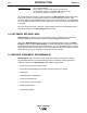
INTRODUCTION Section 1 1-1 KEY TOPICS This symbol indicates the location of key concepts throughout this manual. 1.1 PRODUCT OVERVIEW Wave Designer is a visual, interactive software application used to modify wave shapes for use with programmable waveform-controlled welding machines such as the Power Wave 455. The Wave Designer software package includes a standard set of waveforms commonly used in commercial and industrial welding applications.
INTRODUCTION 1-2 In Windows NT 4.0 Section 1 log on as Administrator Start | Settings | Control Panel | System | Performance Virtual Memory Change... | Initial Size (MB): 100 | Set | OK Do you want to restart your computer now? Yes An RS-232 serial communication cable is required to use Wave Designer software with Power Wave power sources. The Power Wave requires an RS-232 DB25 male connector. Most computers feature an RS-232 DB-9 female connector as the COM serial port. (e.g. Radio Shack cat no.
SOFTWARE INSTALLATION Section 2 2-1 2.1 FILE STORAGE LOCATIONS The Wave Designer default home directory is C:\Program Files\WaveDesigner.
2-2 SOFTWARE INSTALLATION Section 2 FIGURE 2-1. WAVE DESIGNER STARTUP SCREEN. Welcome to Wave Designer Lincoln Electric Wave Designer Version 1.0 Copyright © 1998 The Lincoln Electric Company All Rights Reserved Wave Designer WARNING: This computer program is protected by copyright law and international treaties. Unauthorized reproduction or distribution of this program, or any part of it, may be prosecuted to the maximum extent possible under the law.
Section 2 SOFTWARE INSTALLATION 2-3 PLEASE NOTE: Some IBM ThinkPads® by default have the serial port disabled and instead the port is used for infrared. The following information describes the procedure to disable the infrared feature and enable the serial port. Follow the instructions below to use COM1 to communicate with the PowerWave. More instructions at the end discuss how to use other ports, if necessary. The following information can also be found at the IBM website at http://www.pc.ibm.
SOFTWARE INSTALLATION 2-4 Section 2 2.4 EQUIPMENT/SOFTWARE STARTUP When the Wave Designer software installation is complete, Wave Designer is listed among the programs you can start up from the Windows startup screen. Click on START, point to the programs option, then click on the Wave Designer option. The Wave Designer Welcome screen is displayed followed by the Pulse Waveform Editor screen. When the Pulse Waveform Editor screen is displayed, the software is ready for use.
SOFTWARE OPERATION Section 3 3-1 3.1 SYNERGIC WELDING AND WORKPOINTS Prior to using Wave Designer it is important to have a good understanding of the concepts of synergic welding and workpoints. Synergic welding is basically “one knob control” of a welding process; all other variables of the process are adjusted by the power source based on the single controlling variable. This single controlling variable is known as a workpoint.
SOFTWARE OPERATION 3-2 Section 3 3.2 WORKING IN WAVE DESIGNER 3.2.1 WAVEFORM EDITOR WINDOW Refer to the Waveform Editor window in Figure 3-2 and the related usage instructions. FIGURE 3-2. WAVEFORM EDITOR WINDOW. 1 4 Wave Designer Pro Off Line - pulse.swf File 2 Tools Print Help Pulse Waveform Editor 50 Wire Feed Speed 3 Edit 700 600 Ramp Up Rate 600 500 Ramp Overshoot % -20 400 Peak Amps 250 300 Peak Time ms 1.2 Tailout Time 3.0 200 100 Tailout Speed .
Section 3 SOFTWARE OPERATION 3-3 5. Optional Windows The optional window buttons open additional windows used during wave shaping. Optional windows in the pulse Waveform Editor include Start, Adapt, Short, End, and About. Details about the use of most optional windows is covered in the applicable appendix (i.e. Appendix A for Pulse Wave Shaping). We use the About window shown in Figure 3-3 to record descriptive weld application data for custom wave shape files.
3-4 SOFTWARE OPERATION Section 3 3.2.2 WAVEFORM EDITOR TOOL BAR There are four menu selections available on the pulse waveform editor tool bar. The following describes how to use the File, Tools, and Print menus. The Help menu is self explanatory. 3.2.2.1 FILE MENU File The File menu provides options for accessing and managing waveform data files.
Section 3 SOFTWARE OPERATION 3.2.2.2 TOOLS MENU Tools The Tools menu includes waveform display options and other tools required to operate Wave Designer. The Tools menu options include the following: 3-5 Print Help Pulse Editor Ctrl+P STT Editor Ctrl+E Simplify Editor Ctrl+A ArcScope Pulse Editor Ctrl+P Display the Pulse Waveform Editor screen. Flash Custom Waveform Ctrl+F Browse Mode Directory STT Editor Ctrl+E Display the STT Waveform Editor screen.
SOFTWARE OPERATION 3-6 Section 3 3.2.2.3 PRINT MENU Print menu options enable you to print out a waveform display, ArcScope screen, or tabular waveform data listing as shown below. The Print menu options include the following: Wave Designer Pro Waveform Editor Printed on Thu Jul 09 07:24:50 EDT 1998 ..\systemWeldFile\pulse.
SOFTWARE OPERATION Section 3 3-7 3.2.3 EDITING AND SELECTING WORKPOINTS For each custom welding application, unique wave shapes are developed for specific workpoints within the range of workpoints defined for the application. In Wave Designer the range of workpoints and the specific workpoint values are defined in a Workpoint Editor window. After the workpoints are defined, we use a workpoint pulldown menu to select a specific workpoint for wave shaping.
SOFTWARE OPERATION 3-8 Section 3 3.2.3.1 EDITING WORKPOINTS Clicking on the Edit button in the waveform Editor window opens a Workpoint Editor window. The Workpoint Editor window displays a listing of workpoints for the selected standard waveform. Use the Workpoint Editor window according to the following descriptions and guidelines: • • • • WorkPoint Editor Each workpoint value must be equal to or greater than the preceding workpoint value.
SOFTWARE OPERATION Section 3 3-9 3.2.3.2 SELECTING WORKPOINTS Clicking on the workpoint display box in the waveform Editor window opens a Workpoint pulldown menu. The pulldown menu displays the listing of workpoints defined for the active waveform. Use the pulldown menu according to the following descriptions and guidelines: • Click on any one of the listed workpoints to access the related waveform.
3-10 SOFTWARE OPERATION Section 3 3.2.4 EDITING VARIABLE PARAMETERS The following is a summary of the different methods available for changing (editing) parameter values on the Waveform Editor screen and other display screens accessible through Wave Designer. Read the following information carefully before making parameter changes on the Waveform Editor screen. • The variable editor and wave shape graphic functions are interrelated.
Section 3 SOFTWARE OPERATION 3-11 3.3 WAVE DESIGN PROCESS The wave design process is a series of operations that allows you to quickly modify a standard waveform to fit your specific welding application. The following process flowchart applies to a pulse waveform, but is similar to the process used to modify STT and other waveforms. Examples of each process step can be found in the listed reference paragraphs.
SOFTWARE OPERATION 3-12 Section 3 3.4 DOWNLOADING WAVE SHAPES The Power Wave stores wave shapes in the welding machine controller memory. The memory structure does not allow an upload or download of individual wave shapes. When downloading wave shapes to the welding machine, the entire welding machine memory must be overwritten. Each wave shape must be re-selected for download to the flash memory.
SOFTWARE OPERATION Section 3 3-13 2. Select a blank Mode or a defined Mode for overwrite by clicking on a box to the left of the Modes listing. When the Mode is selected, a checkmark appears in the Mode box. 3. Enter the file name of the desired waveform in the box to the right of the selected Mode number. Click on the Choose button to find the exact name of the weld file(s) you wish to download. Click on the weld file name to select the file for download. 4.
3-14 SOFTWARE OPERATION WAVE DESIGNER Section 3
ARCSCOPE Section 4 4-1 4.1 INTRODUCTION The following describes the ArcScope application included with Wave Designer Pro. The ArcScope application provides oscilloscope type displays of power source output waveforms on your computer monitor. 4.1.1 USING THE ARC SCOPE WINDOW Refer to the ArcScope window in Figure 4-1 and the related window usage instructions. FIGURE 4-1. ARC SCOPE WINDOW. Wave Designer Pro Off Line - pulse.
ARCSCOPE 4-2 Section 4 6. Status Bar The status bar provides a scrolled listing of recent Wave Designer program operations, error conditions, etc., and three operational status indicators. The adaptive indicator is also a button that toggles between the Adaptive and Non-Adaptive mode. 7. Graphical Display Area The graphical display provides refreshed displays of the selected waveforms from the output of the connected power source.
Section 4 ARCSCOPE File | Save Scope: Use the Save Scope option to save the scope trace data in ASCII text format for use in a word editor or spreadsheet data processing application. File | Open Scope Trace: Use the Open Scope Trace option to open a saved scope trace data file. 4-3 File Tools Print Open Waveform Help Ctrl+O Save Waveform As ... Save Waveform Ctrl+S Open Scope Trace Save Scope As ...
4-4 ARCSCOPE WAVE DESIGNER Section 4
TROUBLESHOOTING Section 5 5-1 5.1 OVERVIEW Wave Designer troubleshooting is limited to the software application. If the welding machine does not respond, recheck the interface connection and communication setup requirements in section 2 of this manual. Refer to the welding machine service manuals for troubleshooting suspected equipment malfunctions. 5.
5-2 TROUBLESHOOTING WAVE DESIGNER Section 5
PULSE WAVE SHAPING PRINCIPLES Appendix A A-1 A.1 APPENDIX OVERVIEW This appendix provides a series of discussions on pulse wave shaping principles and the development of custom GMAW pulse waveforms. The contents of this appendix are arranged as follows: Paragraph No./Title Contents Description A.2 GMAW Pulse Overview How the pulse waveform transfers weld droplets to the weld surface A.3 Adaptive and Non-Adaptive Mode How WFS and primary wave shape parameters effect welding A.
A-2 PULSE WAVE SHAPING PRINCIPLES Appendix A A.2 GMAW PULSE OVERVIEW Figure A-1 illustrates the variables of the GMAW-P welding process. Each of these variables can be programmed into a weld table using the Wave Designer software. Figure A-2 shows how the pulse waveform and the primary variables shape, detach and propel a weld droplet across the arc. For more details on each of these variables, refer to Primary Pulse Waveform Components and Secondary Pulse Waveform Components in paragraphs A.5 and A.
PULSE WAVE SHAPING PRINCIPLES Appendix A A-3 FIGURE A-2. WELD DROPLET TRANSFER. SPRAY TRANSITION CURRENT RAM P-UP R ATE PEAK AMPS TAILOUT BACKGROUND AMPS T1 T2 T3 T4 T5 WELD DROPLET TRANSFER 27850028 • From time T1 to T2: Background current maintains an arc, and a weld bead starts to form. • From time T2 to T3: Ramp-up current forms the weld droplet at the tip of the electrode. • From time T3 to T4: Peak current and peak time separate the droplet and propel it toward the weld surface.
A-4 PULSE WAVE SHAPING PRINCIPLES Appendix A A.3 ADAPTIVE AND NON-ADAPTIVE MODE To proficiently develop welding procedures using Wave Designer, the key concept of Adaptive versus Non-Adaptive welding must be understood. Wave Designer allows the user to set the machine into either adaptive or non-adaptive mode. During the wave design process both modes will be used depending upon the step. A.3.1 ADAPTIVE MODE In normal synergic welding the Power Wave welds in the adaptive mode.
Appendix A PULSE WAVE SHAPING PRINCIPLES A-5 A.4 PULSE WAVE DESIGN PROCESS The Wave Designer software interfaces with the welding machine controller to permit real time communication of pulse wave design changes. Refer to paragraph 2.3 for equipment interface connections. Use the following wave design process to customize a standard wave shape. The process is summarized in the following flowchart. The flowchart is followed by a detailed process description.
A-6 PULSE WAVE SHAPING PRINCIPLES Appendix A A.4.1 SELECTING A STARTING WAVE SHAPE When customizing a waveform for a specific welding application, we recommend that you use a waveform in an existing weld file. An existing weld file can be selected from the systemWeldFiles folder in the Wave Designer directory as follows: a. Click on a standard wave shape from the systemWeldFiles folder. Use the load file option in the File menu to download the selected file to the Pulse Waveform Editor.
Appendix A PULSE WAVE SHAPING PRINCIPLES A-7 A.4.2 CUSTOMIZING THE WAVE SHAPE If customizing your first wave shape, perform the wave shaping exercises provided at the back of this section to get thoroughly acquainted with wave shaping. Thereafter, refer to the following wave shaping procedure. 1. Select a Workpoint a. Select a workpoint from the Wire Feed Speed pulldown menu. The first workpoint selected should be in the midrange of the expected Wire Feed Speeds to be used for the weld application.
PULSE WAVE SHAPING PRINCIPLES Appendix A 2. Open the Adaptive Loop / Find the Optimal Arc Characteristics Use the following weld trials and adjustment sequence to tune the selected waveform for your weld application at the designated workpoint (wire feed speed). Weld trials and adjustments are more easily performed with one person welding while you adjust the waveform parameters at the computer terminal. a. Click on the button to open the Adapting Stickout screen.
PULSE WAVE SHAPING PRINCIPLES Appendix A A-9 3. Close the Adaptive Loop / Adjust the Peak Voltage a. If the adaptive stickout window is not open, click on the button to open the window. Select the adaptive option to close the adaptive loop. Verify that the adaptive button lights up. NOTE: When on-line with the adaptive loop closed, the wave shape parameters will be adapted (change) to maintain constant arc length.
A-10 PULSE WAVE SHAPING PRINCIPLES Appendix A 5. Adjust the Start Control Parameters (Optional) The start control parameters can be adjusted to define how the welding machine will respond when the arc is struck. To view the start control window, click on the button on the Waveform Editor screen. Adjust the start control parameters to accommodate your welding application and per the following parameter descriptions.
PULSE WAVE SHAPING PRINCIPLES Appendix A A-11 6. Adjust the Shorting Control Parameters (Optional) The shorting control parameters can be adjusted to define how the welding machine will respond when the arc shorts to the weld puddle. To view the shorting control window, click on the button on the Waveform Editor screen. Adjust the shorting control parameters to accommodate your welding application and per the following parameter descriptions.
A-12 PULSE WAVE SHAPING PRINCIPLES Appendix A 7. Adjust the End Condition Parameters (Optional) The end condition parameters can be adjusted to define how the welding machine will respond at the end of a weld application. To view the end condition window, click on the button on the Waveform Editor screen. Adjust the end condition parameters to accommodate your welding application and per the following parameter descriptions.
PULSE WAVE SHAPING PRINCIPLES Appendix A A-13 8. “Go Figure” / Make the Waveform Synergic Weld synergy is established by shaping the 2nd and all subsequent workpoints. Being synergic, the waveform parameters automatically adjust to programmed data table values. The data table values are unique for selected wire feed speeds. Thereby, the output of the power source changes in response to changes in the wire feed speed, as controlled by the PowerWave’s WFS encoder setting.
A-14 PULSE WAVE SHAPING PRINCIPLES Appendix A A.5 PRIMARY PULSE WAVEFORM COMPONENTS The following paragraphs describe how peak current, peak time, frequency, and background current effect weld droplet transfer. A.5.1 PEAK CURRENT AND PEAK TIME A combination of peak current and peak time, Figure A-6, applies a force to detach the weld droplet from the electrode and propel it across the arc. Transition current is the current level required to achieve weld droplet formation.
Appendix A PULSE WAVE SHAPING PRINCIPLES A-15 A.5.2 FREQUENCY Frequency, Figure A-7, is the number of pulses per second or, in theory, the number of weld droplets per second. Since increasing the frequency generates more pulses in a given time period, higher frequencies generate higher average current levels. FIGURE A-7. FREQUENCY. AVERAGE CURRENT BACKGROUND CURRENT T1 T2 T3 T2 T3 LARGER DROPLETS SHORTER ARC AVERAGE CURRENT BACKGROUND CURRENT T1 SMALLER DROPLETS LONGER ARC 27850040 A.5.
A-16 PULSE WAVE SHAPING PRINCIPLES Appendix A A.6 SECONDARY WAVEFORM PARAMETERS A.6.1 RAMP-UP RATE The ramp-up rate is the speed of current climb from the background current level to the peak current level. Faster ramp-up rates tend to produce a plasma plume that quickly surrounds the end of the next droplet. A.6.2 RAMP OVERSHOOT % The ramp overshoot % can be set from -100% to +100% of the peak amps value. Positive % overshoot is commonly used to harden the arc.
Appendix A PULSE WAVE SHAPING PRINCIPLES A-17 A.7 APPLICATION EXERCISE This application exercise steps the user through the development of a basic PowerWave welding program using Wave Designer. Your application most likely will vary from this example but the concepts outlined are recommended for all development work.
A-18 PULSE WAVE SHAPING PRINCIPLES 3. Using the adaptive stickout window or the green adaptive button on the status bar, select ‘No Adapt’. The status bar at the bottom of the screen should read: . Close the “adapt” window (if opened). Appendix A Adapting Stickout Adapting Stickout For Wire Feed Speed 150 No Adapt: Maintain constant wire extension Adaptive: Maintain constant arc length 4. While welding, adjust the pulse variables to improve welding performance. Maintain a constant 5/8 in.
Appendix A PULSE WAVE SHAPING PRINCIPLES 6. The “Start”, “Short”, and “End” windows can be adjusted at this time to optimize the starting, shorting, and ending routines. A-19 Start Control - Pulse Start Control 150 For Wire Feed Speed Our Experiment: We needed to adjust the starting variables. With the feeder’s run-in WFS set at 65 in/min, we set the starting variables to control the starting routine. With the assistance of ArcScope, we found good settings with these values: start volt 21.
A-20 PULSE WAVE SHAPING PRINCIPLES Appendix A 8. For a second workpoint we went to 300 in/min. Select the 300 in/min. wire feed speed from the pulldown menu in Waveform Editor window. Reset the PowerFeed for 300 in/min. with a 1.00 trim. 9. Open the adapting stickout window and select the ‘No Adapt’ mode; close the window. 10. At lower wire feed speed settings, some users like to fix the values of the peak variables.
PULSE WAVE SHAPING PRINCIPLES Appendix A 12. Open the “Edit” screen and select only those workpoints that have been developed (150 and 300 in/min.). Select the button to interpolate the remaining workpoints. The function gives a estimation of the values needed for the other wire feed speeds. Each useable workpoint should be developed separately. Our Experiment: We tested the 205 in/min. workpoint to confirm that its operation was good.
A-22 PULSE WAVE SHAPING PRINCIPLES WAVE DESIGNER Appendix A
STT WAVE SHAPING PRINCIPLES Appendix B B-1 B.1 APPENDIX OVERVIEW This appendix provides a series of discussions on STT wave shaping principles and the development of custom STT waveforms. The contents of this appendix are arranged as follows: Paragraph No./Title Contents Description B.2 STT Overview How the STT waveform transfers weld droplets to the weld surface B.3 STT (Surface Tension Transfer) How WFS and wave shape parameters effect welding B.
STT WAVE SHAPING PRINCIPLES B-2 Appendix B B.2 STT OVERVIEW Figure B-1 illustrates the variables of the STT welding process. Each of these variables can be programmed into a weld table using the Wave Designer software. Figure B-2 shows how the STT waveform and the primary variables produce a weld. For more details on each of these variables, refer to Primary STT Waveform Components and Secondary STT Waveform Components in paragraphs B.5 and B.6 of this appendix. FIGURE B-1. STT WAVEFORM PARAMETERS.
STT WAVE SHAPING PRINCIPLES Appendix B B-3 FIGURE B-2. WELD DROPLET TRANSFER. AM PS PEAK AMPS PI NC H TAILOUT BACKGROUND AMPS T0 T1 T2 T3 T5 T6 T7 27850060 • From time T0 to T1: Background current is a steady-state current level, between 50 and (Background Current) 100 Amps that maintains an arc to form a weld bead. • From time T1 to T2: (Ball Time) An arc voltage detector indicates that the arc is shorted; background current is reduced for approximately 0.75 milliseconds.
STT WAVE SHAPING PRINCIPLES B-4 Appendix B B.3 STT (SURFACE TENSION TRANSFER) The Invertec STT power source is a high-frequency, current-controlled machine that delivers power to the arc based on immediate arc requirements. The Invertec STT produces large electrode current changes within microseconds. It operates in the short-circuiting welding mode. The electrode current supplied by the power source is guided by the arc voltage state.
STT WAVE SHAPING PRINCIPLES Appendix B B-5 T2 – T3 The pinch mode applies an increasing, dual-slope ramp of current to the shorted electrode. The dual slope ramp of current accelerates the transfer of molten metal by the electric pinch forces. The pinch force is directly proportional to the square of the pinch current. T3 – T5 dV/dt is the rate of shorted-electrode voltage change per unit time. On-going dV/dt calculations are performed electronically during the pinch mode.
B-6 STT WAVE SHAPING PRINCIPLES Appendix B B.4 STT WAVE DESIGN PROCESS The Wave Designer software interfaces with the welding machine controller to permit real time communication of STT wave design changes. Refer to paragraph 2.3 for equipment interface connections. Use the wave design process to customize a standard wave shape. The process is summarized in Figure B-4. The flowchart is followed by a detailed process description.
Appendix B STT WAVE SHAPING PRINCIPLES B-7 B.4.1 SELECTING A STARTING WAVE SHAPE When customizing a waveform for a specific welding application, we recommend that you use a waveform in an existing weld file. An existing weld file can be selected from the systemWeldFiles folder in the Wave Designer directory as follows: a. Click on a standard wave shape from the systemWeldFiles folder. Use the load file option in the File menu to download the selected file to the STT Waveform Editor.
B-8 STT WAVE SHAPING PRINCIPLES Appendix B B.4.2 CUSTOMIZING THE WAVE SHAPE If customizing your first wave shape, perform the wave shaping exercises provided at the back of this section to get thoroughly acquainted with wave shaping. Thereafter, refer the following wave shaping procedure. 1. Select a Workpoint a. Select a workpoint from the Wire Feed Speed pulldown menu. The first workpoint selected should be in the midrange of the expected Wire Feed Speeds to be used for the weld application.
STT WAVE SHAPING PRINCIPLES Appendix B B-9 2. Find the Optimal Arc Characteristics Use the following weld trials and adjustment sequence to tune the selected waveform for your weld application at the designated workpoint (wire feed speed). Weld trials and adjustments are more easily performed with one person welding while you adjust the waveform parameters at the computer terminal. a. Set the Invertec Trim control for a readout of 1.00.
STT WAVE SHAPING PRINCIPLES B-10 Appendix B 3. Adjust the Start Control Parameters (Optional) The start control parameters can be adjusted to define how the welding machine will respond when the arc is struck. To view the start control window, click on the button on the Waveform Editor screen. Adjust the start control parameters to accommodate your welding application and per the following parameter descriptions.
STT WAVE SHAPING PRINCIPLES Appendix B B-11 4. “Go Figure” / Make the Waveform Synergic Weld synergy is established by shaping the 2nd and all subsequent workpoints. Being synergic, the waveform parameters automatically adjust to programmed data table values. The data table values are unique for selected wire feed speeds. Thereby, the output of the power source changes in response to changes in the wire feed speed, as controlled by the Invertec’s WFS encoder setting.
B-12 STT WAVE SHAPING PRINCIPLES Appendix B B.5 PRIMARY STT WAVEFORM COMPONENTS The following paragraphs describe how peak current, background current, and tailout effect weld droplet transfer. B.5.1 PEAK CURRENT The peak current control acts similar to an “arc pinch” control. Peak current serves to establish the arc length and promote good fusion. Higher peak current levels will cause the arc to broaden momentarily while increasing the arc length.
Appendix B STT WAVE SHAPING PRINCIPLES B-13 B.5.2 BACKGROUND CURRENT The Background current controls the overall heat input to the weld. Adjusting this level too high will form a large droplet resulting in globular type transfer and increased spatter. Adjusting this level too low will cause wire stubbing and poor wetting of the weld metal.
B-14 STT WAVE SHAPING PRINCIPLES Appendix B B.6 SECONDARY STT WAVEFORM COMPONENTS NOTE: The Invertec STT power source circuitry automatically establishes proper values for most primary and secondary waveform components. The values can be adjusted, but should not be set far from their automatically set values. B.6.1 PINCH START The pinch start is the amperage setting that begins the ramp up to the maximum pinch current. Pinch start current must exceed background current. B.6.
STT WAVE SHAPING PRINCIPLES Appendix B B-15 B.7 APPLICATION EXERCISE This application exercise steps the user through the development of a basic PowerWave/STT welding program using Wave Designer. Your application most likely will vary from this example but the concepts outlined are recommended for all development work.
B-16 STT WAVE SHAPING PRINCIPLES 2. Pick a wire feed speed from the Wire Feed Speed pulldown menu. We wanted to start with a 130 in/min. WFS. But 130 is not a workpoint in the selected wave shape application. Use the Workpoint Editor window to change the second workpoint (170 in/min.) to 130. Appendix B WorkPoint Editor WorkPoint Editor 0 90 1 130 2 200 3 225 inch / min meter / min Go Figure 28750067 3. Select 130 from the Wire Feed Speed pulldown menu.
Index-1 INDEX A Adaptive Loop .......................................................................................................... Adaptive Types ........................................................................................................ Adaptive and Non-Adaptive Mode ........................................................................... Amp • Time ..............................................................................................................
Index-2 INDEX M Making the Waveform Synergic .............................................................................. A-13 O Open Circuit Voltage ................................................................................................ A-10 Operation, Software ................................................................................................ 3-2 P Peak Current ..........................................................................................
Index-3 INDEX U Upgrade Firmware .................................................................................................. User Responsibility .................................................................................................. 2-5 1-1 V Voltage, Arc Reestablish ................................................................................................ Open Circuit ...................................................................................................... Peak .....
Index-4 INDEX WAVEDESIGNER