
DESIGNER IM649 User guide


A-2 Appendix A
PULSE WAVE SHAPING PRINCIPLES
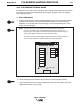
WAVE DESIGNER
Pulse Waveform Editor
Wire Feed Speed
Ramp Up Rate
Peak Amps
Peak Time ms
Tailout Time
Tailout Speed
Stepoff Amps
Backgrd Amps
Backgrd Time
Frequency
Ramp Overshoot %
26.4
33.4
21
40
.100
3.0
1.2
250
-20
600
Edit
Start
About
Adapt
Short
End
Wave Designer Pro Off Line - pulse.swf
700
600
500
400
300
200
100
0
0 3 6 9 12 15 18 21 24 27 30
File Tools Print Help
50
Off Line Stand by
27850027
Status
AC.sco loaded
Adaptive
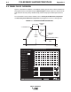
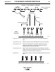
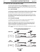
A.2 GMAW PULSE OVERVIEW
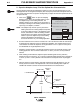
Figure A-1 illustrates the variables of the GMAW-P welding process. Each of these variables can
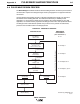
be programmed into a weld table using the Wave Designer software. Figure A-2 shows how the
pulse waveform and the primary variables shape, detach and propel a weld droplet across the
arc.
For more details on each of these variables, refer to
Primary Pulse Waveform Components
and
Secondary Pulse Waveform Components
in paragraphs A.5 and A.6 of this appendix.
FIGURE A-1. PULSE WAVEFORM PARAMETERS.
27850026
RAMP-UP RATE
TAILOUT
SPEED
TAILOUT
TIME
STEP-OFF
AMPS
BACKGROUND
TIME
BACKGROUND AMPS
1/FREQUENCY
% OVERSHOOT
PEAK TIME
PEAK
AMPS