
DESIGNER IM649 User guide


Appendix A A-21
PULSE WAVE SHAPING PRINCIPLES
WAVE DESIGNER
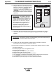
12. Open the “Edit” screen and select only those
workpoints that have been developed (150 and
300 in/min.). Select the button to
interpolate the remaining workpoints. The
function gives a estimation of the
values needed for the other wire feed speeds.
Each useable workpoint should be developed
separately.
WorkPoint Editor
WorkPoint Editor
1
0
2
3
4
5
6
7
8
9
10
11
50 700
80 850
110 1000
150 1200
205
300
400
600
inch / min meter / min
Go Figure
28750046
Our Experiment: We tested the 205 in/min.
workpoint to confirm that its operation was
good. We checked the pulse variables in the
no adapt mode and the peak voltage in the
adaptive mode. The 205 in/min. workpoint
was acceptable without modifications. The
other workpoints in the program can be
developed in a similar fashion. After we
completed developing the program, we
checked its performance across the range of
wire feed speeds.
13. The specific wire feed speed points of the program are now developed in the range of
150 in/min to 300 in/min. Check the full range of the program to confirm its synergic
operation.
Our Experiment: We started at 150 in/min. and while welding, ran the wire feed speed up to
300 in/min. The arc looked consistent across the range.
14. If desired, our new custom waveform could be ‘Saved As’ another file name and
downloaded into the PowerWave’s weld mode directory.
The new program is complete. To summarize, we performed the following sequence of tasks:
1. Set up the equipment.
2. Selected a program close to our application needs.
3. Selected a wire feed speed.
4. Make program “No Adapt” and set pulse variables.
5. Make program “Adapt” and set arc length.
6. Adjust the starting, shorting, ending routines as needed.
7. Use to interpolate and extrapolate values for the other wire feed speeds.
8. Choose the next wire feed speed to develop and go back to step 4.
9. Weld with the range of the program to confirm operation performance.