
DESIGNER IM649 User guide


B-2 Appendix B
STT WAVE SHAPING PRINCIPLES
WAVE DESIGNER
STT Waveform Editor
Wire Feed Speed
Peak Amps
Tailout Speed
Pinch Start
Pinch | Peak
Peak Time
dV | dt detect
Backgrd Amps
14.00
1.0
.70
140
Edit
Start About
Explain
Wave Designer Pro Off Line - stt.swf
500
400
300
200
100
0
012345678910
File Tools Print Help
90
Off Line Stand by
Status
read template2.map
27850057
.500
60
200
AMPERES
PINCH START
dV/dt CALCULATE
PEAK TIME
PEAK AMPS
TAILOUT
SPEED
BACKGROUND AMPS
TIME
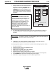
B.2 STT OVERVIEW
Figure B-1 illustrates the variables of the STT welding process. Each of these variables can be
programmed into a weld table using the Wave Designer software. Figure B-2 shows how the
STT waveform and the primary variables produce a weld.
For more details on each of these variables, refer to
Primary STT Waveform Components
and
Secondary STT Waveform Components
in paragraphs B.5 and B.6 of this appendix.
FIGURE B-1. STT WAVEFORM PARAMETERS.