
Welder User Manual

Return to Section TOC Return to Section TOC Return to Section TOC Return to Section TOC
Return to Master TOC Return to Master TOC Return to Master TOC Return to Master TOC
ROTOR “FLASHING” CIRCUIT TEST (continued)
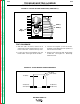
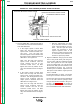
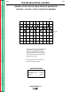
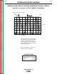
FIGURE F.10 - IDLER P.C. BOARD PIN ASSIGNMENTS
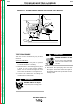
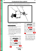
MOVING PARTS can injure.
Keep away from moving parts.
ENGINE EXHAUST can kill.
Use in open, well ventilated
areas or vent exhaust to the
outside.
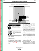
5. Start the engine and run it at High Idle
(3700 - 3800 RPM).
6. The DC ammeter should read between
0.22 and 0.30 amps.
7. If the DC ammeter reads 0.0 amps, check
for flashing voltage between lead #202B
from the brush holder and case ground
(lead #201). See Figure F.8 and the Wiring
Diagram. Normal flashing voltage is 2.05
VDC.
8. If normal flashing voltage is present, per-
form the Rotor Resistance Test. Also be
sure that all #201 leads have continuity
(zero ohms) to case ground.
9. If normal flashing voltage is NOT present
from lead #202 to case ground, check the
continuity of lead #202 to the idler P.C.
board. Also check the continuity of lead
#14 from the engine magneto to the P.C.
board. See Figure F.10 and the Wiring
Diagram.
10. If the above continuity checks are good,
run the engine at high idle (3700 - 3800
RPM). Check for an AC voltage from lead
#14 to case ground. Normal is 3.30 VAC.
If a low or zero AC voltage is indicated,
the engine magneto may be faulty.
Replace.
11. If the AC voltage reading from step 9 is
normal, the idler P.C. board may be faulty.
Replace the idler P.C. board.
12. After the problem has been repaired,
replace the top cover on the control box.
Tighten the 8 sheet metal screws with the
5/16" nut driver.
TROUBLESHOOTING & REPAIR
F-25 F-25
WELDANPOWER 125
WARNING
M17578
WP125 IDLER
16 (BLACK)
9B (BROWN)
14 (WHITE)
203 (RED)
204 (BLACK)
202A (RED)
208 (BROWN)
209 (BROWN)
200A (WHITE)
TO
CURRENT
TRANSFORMER
J1J2