SERVICE MANUAL (INTERNATIONAL) IMPINGER CONVEYOR OVENS MODEL 1421-000-E, 1454, 1455 WITH PUSH BUTTON CONTROLS Lincoln Foodservice Products, LLC 1111 North Hadley Road Fort Wayne, Indiana 46804 United States of America Phone : (800) 374-3004 U.S. Fax: (888) 790-8193 • Int’l Fax: (260) 436-0735 Technical Service Hot Line (800) 678-9511 www.lincolnfp.
SEQUENCE OF OPERATION IMPINGER ADVANTAGE SERIAL NUMBER N28654 AND ABOVE (OVENS WITH PUSH BUTTON CONTROLS) MODEL 1421-000-E POWER SUPPLY CONTROL BOX AUTO COOL DOWN MAIN FAN CIRCUIT HEAT CIRCUIT TEMPERATURE CONTROL CONVEYOR DRIVE 2 230/400 VAC 50 HZ. 3 PHASE Electrical power is to be supplied to the oven by a five conductor service. Brown conductor is hot. Black conductor is hot. Black conductor is hot. Blue conductor is neutral. Green conductor is ground.
SEQUENCE OF OPERATION IMPINGER ADVANTAGE SERIAL NUMBER N28654 AND ABOVE (OVENS WITH PUSH BUTTON CONTROLS) MODEL 1454 MODEL 1455 POWER SUPPLY CONTROL BOX AUTO COOL DOWN MAIN FAN CIRCUIT HEAT CIRCUIT TEMPERATURE CONTROL CONVEYOR DRIVE 220/380VAC 240/415VAC 50 HZ. 50 HZ. 3 PHASE 3 PHASE Electrical power is to be supplied to the oven by a five conductor service. Brown conductor is hot. Black conductor is hot. Black conductor is hot. Blue conductor is neutral. Green conductor is ground.
MODEL 1421-000-E, SERIAL NUMBER N28654 AND ABOVE 4 Impinger I -–Adv Digital – Electric Service Manual - International
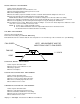
SCHEMATIC DIAGRAM MODEL 1454, 1455 SERIAL NUMBER N28654 AND ABOVE TROUBLESHOOTING GUIDE Impinger I -–Adv Digital – Electric Service Manual - International 5
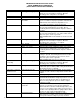
IMPINGER ADVANTAGE ELECTRIC OVENS SERIAL NUMBER N28654 AND ABOVE (OVENS WITH PUSH BUTTON CONTROLS) SYMPTOM Oven fan will not run POSSIBLE CAUSE Incoming power supply Fuse, 10 Amp Fuse holder Thermostat, control box hi-limit Switch, oven power Motor, main fan No control box cooling Incoming power supply Fuse, 10 Amp Fuse holder Switch, oven power Cooling fan No automatic control box cooling Incoming power supply Cooling fan thermostat Control box cooling fan continues to run Cooling fan thermostat
Oven control Contactor, hi-limit (Model 1421-000-E only) Thermocouple Oven control Thermocouple Oven control Heat contactor Intermittent heating Thermal/overload of main fan motor Conveyor will not run Incoming power supply 24VAC at transformer secondary. If there is primary voltage, but no secondary voltage, replace control transformer. Check for 24VAC supply to oven control. If no voltage is present, trace wiring back to control transformer. Check for supply voltage to oven control.
Fuse, 10 Amp Fuse holder Switch, oven power Control transformer Conveyor motor Capacitor, conveyor motor Switch, conveyor reversing Oven control Conveyor motor runs, but there is no speed display NOTE: Display will indicate “BELT JAM” Oven control Conveyor motor Oven control plug to be sure it is firmly in receptacle. Measure incoming power, call power co. if required. Check, replace if necessary. Check, replace if necessary. Check for line voltage supplied to switch.
MOTOR, MAIN FAN - REPLACEMENT 1. Shut off power at main breaker. 2. Remove louvered motor cover from back of oven. 3. Remove wireway by taking out the (5) five hex screws. 4. Disconnect wiring from motor. 5. Remove the twelve (12) hex head bolts from the oven back and slide back straight out of the oven. 6. Remove two (2) bolts from fan hub and remove fan from motor shaft. NOTE: Measure distance from fan blade to rear wall assembly before removal to aid in reassembly. 7.
THERMOSTAT, OVEN CAVITY HI-LIMIT – REPLACEMENT 1. Shut off power at main breaker. 2. Remove control box cover and front panel. Remove conveyor assembly and fingers from oven to aid in removal of thermostat from oven. 3. Disconnect wires from thermostat and mark for reassembly. 4. Remove thermostat from oven. 5. Reassemble in reverse order and check system operation. AIR PRESSURE SWITCH – REPLACEMENT 1. Shut off power at main breaker. 2. Remove control panel top and front cover. 3.
CONTROL TRANSFORMER - REPLACEMENT 1. Shut power off at main breaker. 2. Remove control panel top and front cover. 3. Remove two (2) wires on primary side, note color and location. 4. Remove two (2) wires on secondary side, note color and location. 5. Remove two (2) screws from transformer base and replace assembly. 6. Reinstall in reverse order and check system operation. CONVEYOR DRIVE MOTOR - REPLACEMENT 1. Shut power off at main breaker. 2. Remove control panel top and front cover. 3.
F. G. (included with the oven control) by pushing the extensions onto the four set buttons on control. Reassemble in reverse order and check system operation. Set the oven control for the proper operating mode. The 1400 series ovens use a single temperature control system. The oven control must be set to the proper operating mode. Set the control as follows: With the oven power switch “off”, depress the “time” and “up” buttons and turn the oven “on”.
THERMOSTAT, CONTROL BOX HI-LIMIT – REPLACEMENT 1. 2. 3. 4. 5. Shut off power at main breaker. Remove control box cover and front panel. Remove wiring from thermostat and mark for reassembly. Remove mounting screws and remove thermostat. Reassemble in reverse order and check system operation. NOTE: Be sure to press reset button on new thermostat to set for operation.
GENERAL VIEW ADVANTAGE SERIES LETTER A B C D E F G H J K L M N O P Q R S T U V W X Y Z * AA BB CC DD EE FF GG HH JJ KK LL MM NN OO PP QQ 14 PART NUMBER 369003 369110 369337 369929 369828 369209 369310 369308 369334 369309 350638 369311 369336 369906 370110 369157 1534 369057 369643 1009 369062 369140 369903 369141 369139 369058 369211 369203 369749 369204 369373 369748 369328 369052 369030 369904 369053 369055 369218 369926 369925 369927 DESCRIPTION Door hinge Access window assembly Retainer (old style)
Impinger I -–Adv Digital – Electric Service Manual - International 15
CONTROL BOX 1421-000-E, 1454,1455 LETTER A B C D E F G H I J K L M N O P Q R S T U V W X Y Z AA 16 PART # 369066 370373 369507 369025 369119 369134 370163 370387 370485 369838 357107 369014 369378 369331 370359 369368 370388 370360 4000054 369125 369427 370362 370363 370354 369432 370355 7006831 DESCRIPTION Sprocket, 10 tooth Conveyor motor Thermostat, cooling fan Air pressure switch Terminal block Fuse, 50A Terminal block, 5 Pole Filter, EMI Contactor, mercury Thermostat, control box hi-limit Fuse holde
Impinger I -–Adv Digital – Electric Service Manual - International 17
OVEN BACK ADVANTAGE SERIES GAS AND ELECTRIC LETTER A B C D E F G H J K M 18 PART NUMBER 369808 370140 369214 369033 369215 369192 369306 369646 369647 369213 369547 369287 369315 369122 DESCRIPTION Cover, motor (gas ovens) Cover, motor (electric ovens) Motor, main fan (50 Hz.) Motor clamp Motor support assembly Capacitor, 7.
Impinger I -–Adv Digital – Electric Service Manual - International 19
CONVEYOR 1450 SERIES LETTER A B C D E F G H J K L M 20 PART NUMBER 369830 369816 370092 369825 369813 369314 369812 369160 369814 369811 369161 369806 370050 369162 DESCRIPTION Complete conveyor assembly Conveyor belt Conveyor belt, 1 foot section Retaining ring Conveyor bearing block Roll, conveyor, notched Conveyor idler shaft Conveyor pan stop Connecting link Conveyor drive shaft Roller chain sprocket Crumb pan Conveyor frame Drive chain Impinger I -–Adv Digital – Electric Service Manual - Internatio
Impinger I -–Adv Digital – Electric Service Manual - International 21
This page intentionally left blank.
This page intentionally left blank.
Impinger I -–Adv Digital – Electric Service Manual - International