Contents Before driving Introduction 2 Instrumentation 3 Controls and features 21 Seating and safety restraints 80 Starting and driving Starting 105 Driving 109 Roadside emergencies 123 Servicing Maintenance and care 141 Capacities and specifications 181 Customer assistance 187 Reporting safety defects 199 Index 200 All rights reserved.
Introduction ICONS Indicates a safety alert. Read the following section on Warnings. Indicates vehicle information related to recycling and other environmental concerns will follow. Correct vehicle usage and the authorized disposal of waste cleaning and lubrication materials are significant steps towards protecting the environment. Indicates a message regarding child safety restraints. Refer to Seating and safety restraints for more information.
Instrumentation 3
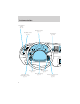
Instrumentation Panel dimmer switch (pg. 21) Instrument cluster (pg. 6) Headlamp control (pg. 21) Gearshift lever (pg. 114) CHECK TRAC 50 60 70 40 80 80 30 60 20 OFF 10 P 100 120 90 140 40 160 180 110 120 H VOL PUSH ON 100 20 MPH km/h SERVICE ENGINE SOON < FILL ON LEFT F 1 2 E AM LO F PANEL DIM S OFF MIST RESUME NEXT SET ACCEL MODE COAST OFF ON TEMP VOL FAN EXT Speed control (pg. 55) Turn signal and wiper/washer control (pg. 55) 4 Climate controls (pg.
Instrumentation Electronic sound system (pg. 28) Clock* (pg. 52) Passenger side air bag (pg. 91) BAL BASS SEL TREB EJ TAPE SEEK RDS SCAN TUNE 1 2 3 REW FF SIDE 1 2 FADE 4 AUTO 5 6 COMP SHUFF RESET SELECT FRONT REAR AUTO MAX A/C Climate control systems (pg. 22) Traction control switch* (pg.
Instrumentation WARNING LIGHTS AND CHIMES CHECK TRAC TRUNK AJAR DOOR AJAR TRAC OFF AIR SUSPENSION CIRCLE SLOWLY 60 COMPASS 20 10 100 120 WASHER LTR/100km 90 140 40 160 100 km MILES/GAL FUEL ECON AVG FUEL REMAIN DIST TO EMPTY AVG SPEED TRIP A B E/M 20 180 110 < FILL ON LEFT 120 H SERVICE ENGINE SOON 70 80 80 30 km O/D OFF TRAC ACTIVE SPEED CONTROL 60 50 40 MPH P F km/h R N D 2 1 AIR BAG 1 2 E BRAKE Service engine soon Your vehicle is equipped with a SERVICE computer that mon
Instrumentation 2. Poor fuel quality or water in the fuel. 3. The fuel cap may not have been properly installed and securely tightened. These temporary malfunctions can be corrected by filling the fuel tank with good quality fuel and/or properly installing and securely tightening the gas cap. After three driving cycles without these or any other temporary malfunctions present, the Service Engine Soon light should turn off.
Instrumentation Brake system warning Momentarily illuminates when the ignition is turned to the ON BRAKE position, the engine is off and the ! parking brake is engaged. If the brake warning lamp does not illuminate at this time, seek service immediately. Illumination after releasing the parking brake indicates low brake fluid level and the brake system should be inspected immediately.
Instrumentation Charging system Illuminates when the ignition is turned to the ON position and the engine is off. The light also illuminates when the battery is not charging properly, requiring electrical system service. Engine oil pressure Momentarily illuminates when the ignition is turned to the ON position and the engine is off. Illuminates when the oil pressure falls below the normal range. Stop the vehicle as soon as safely possible and switch off the engine immediately.
Instrumentation Trunk ajar If the trunk is not completely closed, this light comes on when you turn the ignition to ON. With the ignition ON, this light will flash five times and sound a tone for one second, then remain on. Door ajar Illuminates when one of the doors is not completely shut and the ignition is turned to ON. With the ignition ON, this light will remain on until all doors are closed.
Instrumentation O/D off Illuminates when the transmission control switch (TCS) has been pushed. When the light is on, the transmission does not shift into overdrive. If the light does not come on when the TCS is depressed or if the light flashes when you are driving, have your vehicle serviced. Trac active Illuminates when the Traction Controlt system begins applying and releasing the brakes and adjusting the engine characteristics to limit a wheelspin condition.
Instrumentation Safety belt warning chime Chimes to remind you to fasten your safety belts. For information on the safety belt warning chime, refer to the Seating and safety restraints chapter. Supplemental restraint system (SRS) warning chime For information on the SRS warning chime, refer to the Seating and safety restraints chapter. Key-in-ignition warning chime Sounds when the key is left in the ignition in the OFF/LOCK or ACC position and the driver’s door is opened.
Instrumentation Odometer Registers the total kilometers (miles) of the vehicle. TRUNK AJAR DOOR AJAR TRAC OFF AIR SUSPENSION CIRCLE SLOWLY km O/D OFF TRAC ACTIVE SPEED CONTROL COMPASS Fuel gauge Displays approximately how much < FILL ON LEFT fuel is in the fuel tank (when the key is in the ON position). The fuel F 1 2 gauge may vary slightly when the vehicle is in motion. The ignition should be in the OFF position while E the vehicle is being refueled.
Instrumentation Engine coolant temperature gauge Indicates the temperature of the engine coolant. At normal operating H temperature, the needle remains within the normal area (the area between the “H” and “C”). If it enters the red section, the engine is overheating. Stop the vehicle as soon as safely possible, switch off the engine immediately and let the engine cool. Refer to Engine coolant in the Maintenance and care chapter. Never remove the coolant reservoir cap while the engine is running or hot.
Instrumentation • see how many kilometers/miles WASHER FUEL ECON AVG you can drive before running out LTR/100km FUEL REMAIN of fuel. DIST TO EMPTY AVG SPEED • see how many liters/gallons of TRIP A B fuel remain in the fuel tank. E/M • monitor the average fuel km MILES/GAL economy. • monitor the instantaneous fuel economy. • monitor the average speed. • check the distance traveled during a trip on either Trip A or Trip B.
Instrumentation Compass display (if equipped) The compass reading may be TRUNK AJAR DOOR AJAR affected when you drive near large CIRCLE buildings, bridges, power lines and TRAC OFF AIR SUSPENSION SLOWLY powerful broadcast antenna. km Magnetic or metallic objects placed in, on or near the vehicle may also O/D OFF TRAC ACTIVE affect compass accuracy.
Instrumentation Compass calibration adjustment Perform this adjustment in an open area free from steel structures and high voltage lines. For optimum calibration, turn off all electrical accessories (heater/air conditioning, wipers, etc.) and make sure all vehicle doors are shut. 1. Start the vehicle. 2. Locate the compass module and the CALIBRATION BUTTON mounted on the center rear view mirror post. 3.
Instrumentation Checking your highway fuel economy using the electronic message center display The following procedure will allow you to accurately monitor your actual highway fuel economy. Since this procedure requires the vehicle speed control system to be set to highway speeds, it must be run only on suitable roadways where long distance speed control can be safely maintained.
Instrumentation DIST TO EMPTY (DTE) This function estimates FUEL ECON AVG approximately how far you can drive FUEL REMAIN with the fuel remaining in your tank DIST TO EMPTY under normal driving conditions. AVG SPEED Remember to turn the ignition OFF TRIP A B when refueling your vehicle. E/M Otherwise, the display will not show the addition of fuel for a few kilometers (miles).
Instrumentation E/M When this function is displayed, press the RESET control to change the message center display from metric to English units or from English to metric units.
Controls and features PANEL DIMMER CONTROL Use to adjust the brightness of the instrument panel during headlight and parklamp operation. • Push up to brighten. • Push down to dim. PANEL DIM AUTOLAMP CONTROL The autolamp system provides light OFF P sensitive automatic on-off control of the exterior lights normally controlled by the headlamp control. The autolamp system also keeps the AUTO lights on for a preselected period of LAMP time after the ignition switch is turned to OFF.
Controls and features • the headlamp system is not turned on by another feature such as using the headlamp control or Autolamp. The Daytime Running Light (DRL) system will automatically illuminate the tail lamps and parking lamps at dusk (when the headlamp control is in the OFF position). Since the instrument panel will not be illuminated, turn on the headlamps using the headlamp control. High beams Push forward to activate.
Controls and features Turning the EATC on Press AUTO, any of the override controls or the fan speed control. The EATC will only operate when the ignition is in the ON position. ˚F REAR AUTO EXT OFF AUTO FRONT MAX A/C Turning the EATC off Press OFF. The Outside Temperature (EXT) function will continue to operate until the ignition is turned off. EXT OFF AUTO MAX A/C Automatic operation Press AUTO and select the desired temperature.
Controls and features Temperature selection The display window indicates the selected temperature, function (AUTO or one of the override controls) and manual control of fan speed ( ) if automatic fan speed is not desired. To control the temperature, select any temperature between 18°C (65°F) and 29°C (85°F) by pressing the temperature control. ˚F AUTO FRONT REAR For continuous maximum cooling, push the temperature control until 16°C (60°F) is shown in the display window.
Controls and features Fan speed ( ) When AUTO is pressed, fan speed is adjusted automatically for existing conditions. You can override fan speed at any time. To control fan speed manually, press the fan control to cancel automatic fan speed operation or use the steering wheel fan speed control. Press the control up for higher fan speed or down for lower fan speed. and a bar The display will show graph to indicate manual fan operation and relative speed.
Controls and features • MAX A/C-Uses recirculated air to cool the vehicle. The temperature display will remain unchanged and air will be cooled based on the selected temperature. To exit, press AUTO or any other override controls. MAX A/C is noisier than normal A/C but more economical and will cool the inside of the vehicle faster. Airflow is from the instrument panel registers. This mode can also be used to prevent undesirable odors from entering the vehicle.
Controls and features Displaying outside temperature Press EXT to display the outside air temperature. It will be displayed until EXT is pressed again. EXT OFF AUTO MAX A/C If the selected temperature is changed while the outside temperature is displayed, the new temperature will be displayed for four seconds after it is changed, then the outside temperature will return to the window.
Controls and features • If your vehicle has been parked with the windows closed during hot weather, the air conditioner will do a much faster job of cooling if you drive for two or three minutes with the windows open. This will force most of the hot, stale air out of the vehicle. Then operate the air conditioner as you would normally. • When placing objects on top of your instrument panel, be careful to not place them over the defroster outlets.
Controls and features Volume/power control Press the control to turn the audio system on or off. Turn the control to raise or lower volume. VOL - PUSH ON VOL - PUSH ON If the volume is set above a certain level and the ignition is turned off, the volume will come back on at a “nominal” listening level when the ignition switch is turned back on. AM/FM select The AM/FM select control works in radio and tape modes.
Controls and features Tune adjust The tune control works in radio mode. Tune adjust in radio mode • Press to move to the next SEEK frequency down the band (whether or not a listenable TUNE station is located there). Hold the control to move through the frequencies quickly. to move to the next frequency up the band (whether or not • Press a listenable station is located there). Hold for quick movement. Seek function The seek function control works in radio mode.
Controls and features Setting memory preset stations 1. Select the frequency band with the AM or the FM select control. 2. Select a station. Refer to Tune adjust or Seek function for more information on selecting a station. 3. Press and hold a memory preset control until the sound returns, indicating the station is held in memory on the control you selected. 1 2 3 4 5 6 Bass adjust The bass adjust control allows you to increase or decrease the audio system’s bass output.
Controls and features Speaker balance adjust Speaker sound distribution can be adjusted between the right and left speakers. BAL Speaker fade adjust Speaker sound can be adjusted between the front and rear speakers. FADE Tape select • To enter tape mode while in radio mode, press the TAPE AMS control. CLK TAPE AMS Automatic Music Search The Automatic Music Search feature allows you to quickly locate the beginning of the tape selection CLK being played or to skip to the next selection.
Controls and features selection). The tape deck stops and returns to play mode when the AMS circuit senses a blank section on the tape. In order to ensure proper operation of the AMS feature, the tape MUST have a blank section of at least 4 seconds duration between programs. Rewind The rewind control works in tape SIDE 1 - 2 mode. REW FF To rewind in tape mode, press the REW control.
Controls and features The noise reduction system is manufactured under license from Dolby Laboratories Licensing Corporation. Setting the clock Press CLK to toggle between listening frequencies and clock mode while in radio mode. To set the hour, press and hold the CLK control and press: • • CLK TAPE AMS to decrease hours and to increase hours. SEEK SEEK TUNE TUNE To set the minute, press and hold the CLK control and press: CLK TAPE AMS • • 34 to decrease minutes and to increase minutes.
Controls and features The CLK control will allow you to switch between media display mode (radio station, stereo information, etc.) and clock display mode (time). When in clock mode, the media information will display for ten seconds, when the radio is turned on, and then revert to clock information. Anytime that the media is changed, (new radio station, etc.), the media information will again display for ten seconds before reverting back to the clock.
Controls and features Alpine Audio System with Premium AM/FM Stereo Cassette (CD Changer Compatible) BASS BAL SEL TREB VOL PUSH ON CD TAPE EJ SEEK MUTE AM FM TUNE REW FF SIDE 1-2 1 2 3 RDS SCAN 4 FADE DSP AUTO COMP SHUFF 5 6 Your audio system is equipped with selective lighting, a unique lighting strategy. This lighting feature is operable when the headlamps are illuminated.
Controls and features Volume/power control Press the control to turn the audio system on or off. VOL PUSH ON Turn the control to raise or lower volume. VOL PUSH ON If the volume is set above a certain level and the ignition is turned off, the volume will come back on at a “nominal” listening level when the ignition switch is turned back on. Speed sensitive volume (if equipped) With this feature, radio volume changes automatically and slightly with vehicle speed to compensate for road and wind noise.
Controls and features • to increase volume compensation • to decrease or shut off the volume compensation AM/FM select The AM/FM select control works in radio, tape and CD modes (if equipped). SEL AM FM AM/FM select in radio mode This control allows you to select AM or FM frequency bands. Press the control to switch between AM, FM1 or FM2 memory preset stations. AM/FM select in tape mode Press this control to stop tape play and begin radio play.
Controls and features Tune adjust for CD changer • Press to select the previous TUNE disc in the CD changer. (Play will begin on the first track of the disc unless the CD changer is in shuffle mode.) Refer to Shuffle feature for more information. Hold the control to continue reversing through the discs. • Press to select the next disc in the CD changer. Hold the control to fast-forward through the remaining discs. Seek function The seek function control works in radio, tape or CD mode (if equipped).
Controls and features Scan function The scan function works in radio, tape or CD mode (if equipped). SCAN Scan function in radio mode Press the SCAN control to hear a brief sampling of all listenable stations on the frequency band. Press the SCAN control again to stop the scan mode. Scan function in tape mode Press the SCAN control to hear a short sampling of all selections on the tape. (The tape scans in a forward direction.
Controls and features Autoset memory preset Autoset allows you to set strong radio stations without losing your original manually set preset stations. This feature is helpful on trips when you travel between cities with different radio stations. Starting autoset memory preset 1. Select a frequency using the AM/FM select controls. 2. Press the AUTO control. 3. When the first six strong stations AUTO are filled, the station stored in memory preset control 1 will start playing.
Controls and features Speaker balance adjust Speaker sound distribution can be adjusted between the right and left speakers. Press the BAL control. Use the SEL control to adjust the sound between the speakers. Speaker fade adjust Speaker sound can be adjusted between the front and rear speakers. Press the FADE control. Use the SEL control to adjust the sound between the front and rear speakers.
Controls and features • In CD mode, pressing the REW control for less than three seconds results in slow rewind. Pressing the control for more than three seconds results in fast rewind. Fast forward The fast forward control works in FF tape and CD modes (if equipped). 2 • In the tape mode, tape direction will automatically reverse when the end of the tape is reached. • In CD mode, pressing the control for less than three seconds results in slow forward action.
Controls and features Compression feature Compression adjust brings soft and COMP loud CD passages together for a more consistent listening level. 5 Press the COMP control to activate and deactivate compression adjust. The effect of the feature varies with the music content. Shuffle feature The shuffle feature operates in CD SHUFF mode and plays all tracks on the current disc in random order. If 6 equipped with the CD changer, the shuffle feature continues to the next disc after all tracks are played.
Controls and features • Use the SEL control to select ON or OFF. With the feature on, use the SEEK or SCAN control to find a radio station broadcasting a traffic report (if it is broadcasting RDS data). Program type • Press the RDS control until the FIND program type is displayed. SEL RDS • Use the SEL control to select the program type.
Controls and features • Use the SEL control to select TYPE, NAME or NONE. SEL RDS clock feature Refer to Setting the clock for information. Phone mode This feature allows you to control the factory-installed cellular phone MUTE (if equipped) through the radio controls. • Press the phone/mute control to enter phone mode. The playing media will mute. • Use SEEK, TUNE or radio presets 1 through 6 to select a phone number previously programmed in the phone.
Controls and features • JAZZ CLUB—jazz club with clearly reflected sounds. • HALL—rectangular concert hall capacity of about 2 000 • CHURCH—church with a high vault. • STADIUM—outdoor stadium with a capacity of about 30 000. • NEWS—“voice-only” type of sound with a limited audio band. Press the DSP control until one of the following appears: DSP RDS • ALL SEATS • DRIVER SEAT • REAR SEATS Use the SELECT control to change the equalization to the desired mode.
Controls and features CD changer (if equipped) The CD changer is located in one of the following locations: • in the trunk • in the center console • under the driver’s seat 1. Slide the door to access the CD changer magazine. 2. Press to eject the magazine. 3. Turn the magazine (A) over. 4. Using the disc holder release knob (C), pull the disc holder (B) out of the magazine.
Controls and features A If you pull too hard on the disc holder, the disc holder may come completely out of the magazine. If this happens, reinsert the disc holder back into the magazine while pressing on the lever (A). 5. Line up the CD with the groove of the disc holder. Ensure that the label on the CD faces downwards. 6. Press in on the disc holder until it locks securely into the magazine. If the disc holders are not fully locked into the magazine, the unit will not operate.
Controls and features The CD magazine may be inserted or ejected with the radio power off. ONLY use the magazine supplied with the CD changer, other types will damage the unit. Keep the CD changer door closed. Coins and foreign objects will damage the CD player and void your audio system warranty. Troubleshooting the CD changer (if equipped) The laser beam used in the compact disc player is harmful to the eyes. Do not attempt to disassemble the case.
Controls and features Cleaning cassette player (if equipped) Clean the tape player head with a cassette cleaning cartridge after ten to twelve hours of play in order to maintain the best sound and operation. Cassette and cassette player care • Use only cassettes that are 90 minutes long or less. • Do not expose tapes to direct sunlight, high humidity, extreme heat or extreme cold. Allow tapes that may have been exposed to extreme temperatures to reach a moderate temperature before playing.
Controls and features • Station overload. Weak signals are sometimes captured by stronger signals when you pass a broadcast tower. A stronger signal may temporarily overtake a weaker signal and play while the weak station frequency is displayed. The audio system automatically switches to single channel reception if it will improve the reception of a station normally received in stereo. Audio system warranties and service Refer to the “Warranty Guide” for audio system warranty information.
Controls and features Press the left control to decrease the time displayed. AUXILIARY POWER POINT The auxiliary power point is located under the instrument panel. This outlet should be used in place of the cigarette lighter for optional electrical accessories. BAL BASS SEL VOL PUSH ON CD TREB AM FM EJ TAPE SEEK MUTE 1 2 3 REW FF SIDE 1 2 FADE RDS SCAN TUNE 4 AUTO 5 6 COMP SHUFF RESET SELECT FRONT REAR EXT OFF AUTO MAX A/C POSITIONS OF THE IGNITION 1.
Controls and features KEY SYSTEM The vehicle is equipped with a master key and valet key lock system. The master key will actuate doors, trunk, glove box, ignition and remote trunk release. The valet key (marked “valet”) will actuate doors and ignition only. TILT STEERING Pull the tilt steering control toward you to move the steering wheel up or down. Hold the control while adjusting the wheel to the desired position, then release the control. Never adjust the steering wheel when the vehicle is moving.
Controls and features WINDSHIELD WIPER/WASHER CONTROLS Rotate the windshield wiper control to the desired interval, low or high speed position. The bars of varying length are for intermittent wipers. When in this position rotate the control upward for fast intervals and downward for slow intervals. Push the control on the end of the stalk to activate washer. Push and hold for a longer wash cycle. The washer will automatically shut off after ten seconds of continuous use.
Controls and features Do not shift the gearshift lever into N (Neutral) with the speed control on. To turn speed control off • Press OFF or • Turn off the vehicle ignition. ON OFF Once speed control is switched off, the previously programmed set speed will be erased. To set a speed • Press SET/SET ACC/SET ACCEL. For speed control to operate, the speed control must be ON and the vehicle speed must be greater than 48 km/h (30 mph).
Controls and features Do not use the speed control in heavy traffic or on roads that are winding, slippery, or unpaved. To set a higher set speed • Press and hold SET/SET ACC/ SET ACCEL. Release the control RES when the desired vehicle speed is SET reached or ACCEL • Press and release SET/SET ACC/ COAST SET ACCEL. Each press will increase the set speed by 1.6 km/h (1 mph) or • Accelerate with your accelerator pedal. When the desired vehicle speed is reached, press and release SET/SET ACC/SET ACCEL.
Controls and features To disengage speed control • Depress the brake pedal. Disengaging the speed control will not erase the previously programmed set speed. Pressing OFF will erase the previously programmed set speed. ON OFF To return to a previously set speed • Press RES/RSM/RESUME. For RES/RSM/RESUME to operate, the vehicle speed must be faster than 48 km/h (30 mph).
Controls and features STEERING WHEEL CONTROLS (IF EQUIPPED) These controls allow you to operate some radio and climate control features. Radio control features • Press BAND/MODE to select AM, FM1, FM2, TAPE or CD (if equipped). In Radio mode: • Press MEM/NEXT to select a preset station from memory. NEXT MODE In Tape mode: • Press MEM/NEXT to listen to the next selection on the tape. In CD mode: • Press MEM/NEXT to listen to the next track on the disc.
Controls and features Deactivating overdrive Press the Transmission Control Switch (TCS) located on the end of O/D ON/OFF the gearshift lever. The Transmission Control Indicator Light (TCIL) will illuminate on the instrument cluster. The transmission will operate in gears one through three. To return O/D ON/OFF to normal overdrive mode, press the Transmission Control Switch again. The TCIL will no longer be illuminated. When you shut off and re-start your vehicle, the transmission will (Overdrive) mode.
Controls and features Programming 1. Prepare for programming the HomeLinkt Universal Transceiver by erasing the three factory default codes by holding down the two outside buttons until the red light begins to flash after 20 seconds. Release both buttons. 2. Hold the end of your hand-held transmitter 5–14 cm (2–5 inches) away from the HomeLinkt Universal Transceiver surface (located on your visor) while keeping the red light in view. 3.
Controls and features To program your hand-held transmitters: • continue to hold the button on the HomeLinkt Universal Transceiver. • press and re-press the hand-held transmitter button every two seconds until the red light changes from a slow to a fast flash. Operating the HomeLinkT Universal Transceiver Once programmed, the HomeLinkt Universal Transceiver can be used in place of hand-held transmitters.
Controls and features 3. Press and release the programmed HomeLinkt button. Press and release the HomeLinkt button a second time to complete the training process. (Some garage door openers may require this procedure to be done a third time to complete the training). The 2nd or 3rd press from step 3 will activate the door. The HomeLinkt Universal Transceiver has now been trained to the receiver. The remaining two buttons may now be programmed if this has not previously been done.
Controls and features MOON ROOF (IF EQUIPPED) To open the moon roof: • Press and release the control. • For one-touch operation, press and release the rear portion of the control; this will fully open the moon roof. • To stop one-touch operation at the desired position, press and release the forward portion of the control. To close the moon roof: • Press and hold the front portion of the control. • To close from the vent position, press and hold the rear portion of the control.
Controls and features Do not block the sensor on the backside of the mirror since this may impair proper mirror performance. Press the control to turn the mirror on or off. The mirror will automatically return to the normal state whenever the vehicle is placed in R (Reverse) (when the mirror is on) to ensure a bright clear view when backing up. COMP TRUNK REMOTE CONTROL The remote trunk release control is located on the driver’s door trim panel and can be operated at any time.
Controls and features Fuel filler door override release If the remote release is inoperative, open the trunk, then pull the override release handle located inside the trunk to open the fuel filler door. POWER WINDOWS Express down To make the driver window open fully without holding the window control, press the driver window control completely down and release quickly. Depress again to stop window operation.
Controls and features Accessory delay (if equipped) With accessory delay, the window switches, radio, and moonroof may be used for up to ten minutes after the ignition switch is turned to the OFF position or until any door is opened. POWER DOOR LOCKS Press control to unlock or lock all doors. DOOR LOCK Smart locks With the key in the ignition, in any switch position, and either the driver’s or passenger’s door open, the doors cannot be locked using the front door lock switches.
Controls and features Heated outside mirrors (if equipped) Both mirrors are heated automatically to remove ice, mist and fog when the rear window defrost is activated. Do not remove ice from the mirrors with a scraper or attempt to readjust the mirror glass if it is frozen in place. These actions could cause damage to the glass and mirrors. CHILDPROOF DOOR LOCKS When these locks are set, the rear doors cannot be opened from the inside.
Controls and features • To program position one, move the driver seat to the desired position using the seat controls. Press the SET control. The SET control indicator light will briefly illuminate. While the light is illuminated, press control 1. • To program position two, repeat the previous procedure using control 2. A position can only be set or recalled when the transmission gearshift is in Park or Neutral. A memory seat position may be programmed at any time.
Controls and features Unlocking the doors Press this control to unlock the driver’s door. The interior lamps will illuminate. Press the control a second time within five seconds to unlock all doors. Locking the doors Press this control to lock all doors. The horn will chirp and the parklamps/taillamps will flash to confirm that the control was pressed. This feature can be turned on/off through the following procedure: Complete steps 1-7 within 30 seconds or you must repeat the procedure.
Controls and features Opening the trunk Press the control once to open the trunk. Ensure that the trunk is closed and latched before driving your vehicle. Failure to latch the trunk may cause objects to fall out of the trunk or block the rear view. The remote entry system allows you to open the trunk while the ignition is in any position. However, if the ignition is in the ON position and the gearshift is in D (Drive), the trunk will only open if the vehicle is moving 5 km/h (3 mph) or slower.
Controls and features • nearby radio towers • structures around the vehicle • other vehicles parked next to the vehicle To replace the battery: 1. Twist a thin coin between the two halves of the transmitter near the key ring. DO NOT TAKE THE FRONT PART OF THE TRANSMITTER APART. 2. Place the positive (+) side of new battery in the same orientation. Refer to the diagram inside the transmitter unit. 3. Snap the two halves back together.
Controls and features The system automatically turns off after 25 seconds or when the ignition is turned to the START or ACC position. The inside lights will not turn off if: • they have been turned on with the dimmer control or • any door is open. The battery saver will shut off the interior lamps 30 minutes after the last door is closed.
Controls and features Memory seat/mirrors feature (if equipped) The remote keyless entry system can also control the memory seats/mirrors feature. With this feature, the first two programmed transmitters will recall a different memory position. Press the control once to unlock the driver’s door and move the memory features to the corresponding memory position, just as if you had pressed the memory control in the vehicle. • transmitter #1 will recall memory feature position one.
Controls and features KEYLESS ENTRY SYSTEM (IF EQUIPPED) With the keyless entry keypad, you can: 1 2 3 4 5 6 7 8 9 0 • lock or unlock the vehicle doors without using the key. Your vehicle has a factory-set 5–digit code that operates the keyless entry system. You can also program your own 5–digit personal entry code.
Controls and features You can program up to three personal codes to unlock your vehicle. These codes do not replace the permanent code that the dealership gave you. Erasing personal code To erase all of the personal entry codes programmed to a vehicle: 1. Enter the factory-set code. 1 2 3 4 5 6 7 8 9 0 2. Press 1/2 within 5 seconds of step 1. 3. Press and hold 1/2 for two seconds.
Controls and features Locking doors with the keyless entry system It is not necessary to enter the factory-set code prior to locking all doors. To lock the doors: 1. Press 7/8 and 9/0 at the same time. 1 2 3 4 5 6 7 8 9 0 SECURILOCKY PASSIVE ANTI-THEFT SYSTEM Your vehicle is equipped with a coded-key anti-theft system. Only the correct key will be able to start your vehicle. If your keys are lost or stolen, you must take your vehicle to your dealership for key reprogramming.
Controls and features Spare SecuriLocky keys can be purchased from your dealership and programmed to your SecuriLocky passive anti-theft system. Refer to Programming spare SecuriLocky keys for more information. If one or both of your SecuriLocky keys are lost or stolen and you want to ensure the lost or stolen key will not operate your vehicle, bring your vehicle and all available SecuriLocky keys to your dealership for reinitialization.
Controls and features Procedure to program spare SecuriLockY keys to your vehicle New SecuriLocky keys must have the correct mechanical key cut for your vehicle. Conventional (non-SecuriLocky) keys cannot be programmed to your vehicle. You will need to have two previously programmed SecuriLocky keys and the new unprogrammed SecuriLocky key readily accessible for timely implementation of each step in the procedure. Please read and understand the entire procedure before you begin. 1.
Seating and safety restraints SEATING Head restraints Your vehicle’s seats may be equipped with head restraints which are vertically adjustable. The purpose of these head restraints is to help limit head motion in the event of a rear collision. To properly adjust your head restraints, lift the head restraint so that it is located directly behind your head or as close to that position as possible. Refer to the following to raise and lower the head restraints.
Seating and safety restraints Press the control to recline the seatback forward or backward. Press to move the seat forward or backward. Press to move the front portion of the seat cushion up or down. Press to move the rear portion of the seat cushion up or down.
Seating and safety restraints Adjusting the power seats – seat mounted controls Never adjust the driver’s seat or seatback when the vehicle is moving. The power seat controls are located on the side of the driver’s seat. Press to raise or lower the seat, or to move the seat forward or backward. Heated seats (if equipped) To operate the heated seats: • Slide the control to BACK to heat the seatback only. • Slide the control to BOTH to heat the seatback and the seat cushion.
Seating and safety restraints Using the power lumbar support (if equipped) The power lumbar control is located on the outboard side of the seat. Press one side of the control to adjust firmness. Press the other side of the control to adjust softness. Using the manual recline function (if equipped) Never adjust the driver’s seat or seatback when the vehicle is moving. Do not pile cargo higher than the seatbacks to avoid injuring people in a collision or sudden stop.
Seating and safety restraints Memory seats (if equipped) This system allows automatic SET positioning of the driver seat and outside rearview mirrors to two 2 1 programmable positions. The memory seat control is located on the driver door. • To program position one, move the driver seat to the desired position using the seat controls. Press the SET control. The SET control indicator light will briefly illuminate. While the light is illuminated, press control 1.
Seating and safety restraints All occupants of the vehicle, including the driver, should always properly wear their safety belts, even when an air bag SRS is provided. It is extremely dangerous to ride in a cargo area, inside or outside of a vehicle. In a collision, people riding in these areas are more likely to be seriously injured or killed. Do not allow people to ride in any area of your vehicle that is not equipped with seats and safety belts.
Seating and safety restraints 2. To unfasten, push the release button and remove the tongue from the buckle. The front outboard and rear safety restraints in the vehicle are combination lap and shoulder belts. The front and rear seat passenger safety belts have two types of locking modes described below: Vehicle sensitive mode The vehicle sensitive mode is the normal retractor mode, allowing free shoulder belt length adjustment to your movements and locking in response to vehicle movement.
Seating and safety restraints How to use the automatic locking mode • Buckle the combination lap and shoulder belt. • Grasp the shoulder portion and pull downward until the entire belt is extracted. • Allow the belt to retract. As the belt retracts, you will hear a clicking sound. This indicates the safety belt is now in the automatic locking mode.
Seating and safety restraints Front safety belt height adjustment Your vehicle has safety belt height adjustments for the driver and front passenger. Adjust the height of the shoulder belt so the belt rests across the middle of your shoulder. To lower the shoulder belt height, push the button and slide the height control down. To raise the height of the shoulder belt, slide the height adjuster up. Pull down on the height adjustment assembly to make sure it is locked in place.
Seating and safety restraints Insert the tongue into the correct buckle (the buckle closest to the direction the tongue is coming from). To lengthen the belt, turn the tongue at a right angle to the belt and pull across your lap until it reaches the buckle. To tighten the belt, pull the loose end of the belt through the tongue until it fits snugly across the hips. Shorten and fasten the belt when not in use.
Seating and safety restraints Conditions of operation If... The driver’s safety belt is not buckled before the ignition switch is turned to the ON position... Then... The safety belt warning light illuminates for one to two minutes and the warning chime sounds for four to eight seconds. The safety belt warning light and warning chime turn off. The driver’s safety belt is buckled while the indicator light is illuminated and the warning chime is sounding...
Seating and safety restraints AIR BAG SUPPLEMENTAL RESTRAINT SYSTEM (SRS) CHECK TRAC 50 60 70 40 80 80 30 60 20 OFF 10 P H SERVICE ENGINE SOON 100 BAL BASS 120 90 SEL 140 40 160 VOL PUSH ON 100 TREB FADE 20 180 110 120 MPH km/h < FILL ON CD LEFT F 1 EJ TAPE RDS 2 SEEK MUTE SCAN TUNE AUTO E AM FM 1 2 3 REW FF SIDE 1 2 4 5 6 COMP SHUFF LO F PANEL DIM S OFF MIST RES ON SET ACCEL RESET SELECT OFF COAST FRONT REAR EXT OFF AUTO MAX A/C Important s
Seating and safety restraints Steps you can take to properly position yourself away from the airbag: • Move your seat to the rear as far as you can while still reaching the pedals comfortably. • Recline the seat slightly (one or two degrees) from the upright position. Do not put anything on or over the air bag module. Placing objects on or over the air bag inflation area may cause those objects to be propelled by the air bag into your face and torso causing serious injury.
Seating and safety restraints How does the air bag supplemental restraint system work? The air bag SRS is designed to activate when the vehicle sustains sufficient longitudinal deceleration sufficient to cause the sensors to close an electrical circuit that initiates air bag inflation. The fact that the air bags did not inflate in a collision does not mean that something is wrong with the system. Rather, it means the forces were not of the type sufficient to cause activation.
Seating and safety restraints Several air bag system components get hot after inflation. Do not touch them after inflation. If the air bag is inflated, the air bag will not function again and must be replaced immediately. If the air bag is not replaced, the unrepaired area will increase the risk of injury in a collision. The SRS consists of: • driver and passenger air bag modules (which include the inflators and air bags). • side air bags (if equipped). Refer to Side air bag system later in this chapter.
Seating and safety restraints If any of these things happen, even intermittently, have the SRS serviced at your dealership or by a qualified technician immediately. Unless serviced, the system may not function properly in the event of a collision. Side air bag system (if equipped) Do not place objects or mount equipment on or near the air bag cover on the side of the seatbacks of the front seats or in front seat areas that may come into contact with a deploying air bag.
Seating and safety restraints How does the side air bag system work? The side air bag system consists of the following: • An inflatable nylon bag (air bag) with a gas generator concealed behind the outboard bolster of the driver and front passenger seatbacks. • A special seat cover designed to allow airbag deployment. • The same warning light, electronic control and diagnostic unit as used for the front air bags. • Two crash sensors located under the outboard side of the front seats, attached to the floor.
Seating and safety restraints Several air bag system components get hot after inflation. Do not touch them after inflation. If the side air bag has deployed, the air bag will not function again. The side air bag system (including the seat) must be inspected and serviced by a qualified technician in accordance with the vehicle service manual. If the air bag is not replaced, the unrepaired area will increase the risk of injury in a collision.
Seating and safety restraints Disposal of air bags and air bag equipped vehicles (including pretensioners) For disposal of air bags or air bag equipped vehicles, see your local dealership or qualified technician. Air bags MUST BE disposed of by qualified personnel. SAFETY RESTRAINTS FOR CHILDREN See the following sections for directions on how to properly use safety restraints for children. Also see Air Bag Supplemental Restraint System (SRS) in this chapter for special instructions about using air bags.
Seating and safety restraints If the shoulder belt portion of a combination lap and shoulder belt can be positioned so it does not cross or rest in front of the child’s face or neck, the child should wear the lap and shoulder belt. Moving the child closer to the center of the vehicle may help provide a good shoulder belt fit. Do not leave children, unreliable adults, or pets unattended in your vehicle.
Seating and safety restraints When installing a child safety seat: • Review and follow the information presented in the Air Bag Supplemental Restraint System section in this chapter. • Use the correct safety belt buckle for that seating position. • Insert the belt tongue into the proper buckle until you hear a snap and feel it latch. Make sure the tongue is securely fastened in the buckle.
Seating and safety restraints Installing child safety seats in combination lap and shoulder belt seating positions 1. Position the child safety seat in a seat with a combination lap and shoulder belt. An air bag can kill or injure a child in a child seat. If you must use a forward-facing child seat in the front seat, move seat all the way back. Children 12 and under should be properly restrained in the rear seat whenever possible. 2.
Seating and safety restraints 3. While holding the shoulder and lap belt portions together, route the tongue through the child seat according to the child seat manufacturer’s instructions. Be sure the belt webbing is not twisted. 4. Insert the belt tongue into the proper buckle (the buckle closest to the direction the tongue is coming from) for that seating position until you hear a snap and feel the latch engage. Make sure the tongue is latched securely by pulling on it. 5.
Seating and safety restraints 7. Pull the lap belt portion across the child seat toward the buckle and pull up on the shoulder belt while pushing down with your knee on the child seat. 8. Allow the safety belt to retract to remove any slack in the belt. 9. Before placing the child in the seat, forcibly tilt the seat forward and back to make sure the seat is securely held in place. 10.
Seating and safety restraints Tether anchorage hardware Attachment holes (at each rear seating position) have been provided in your vehicle to attach anchor hardware, if desired. Tether anchorage hardware kits (part number 613D74) including instructions, may be obtained at no charge from any Ford or Lincoln-Mercury dealer. All vehicles built for sale in Canada include a tether anchor hardware kit. Be sure to follow the child safety seat manufacturer’s instructions.
Starting PREPARING TO START YOUR VEHICLE Engine starting is controlled by the ignition system. This system meets all Canadian Interference-Causing Equipment standard requirements regulating the impulse electrical field strength of radio noise. When starting a fuel-injected engine, avoid pressing the accelerator before or during starting. Only use the accelerator when you have difficulty starting the engine. For more information on starting the vehicle, refer to Starting the engine in this chapter.
Starting 2. Make sure the headlamps and vehicle accessories are off. 3. Make sure the parking brake is set. HOOD 4. Make sure the gearshift is in P (Park). 5. Turn the key to 4 (ON) without turning the key to 5 (START).
Starting Make sure the corresponding lights illuminate briefly. If a light fails to illuminate, have the vehicle serviced. • If the driver’s safety belt is fastened, the light ( ) will not illuminate. STARTING THE ENGINE 1. Turn the key to 5 (START) without pressing the accelerator pedal and release as soon as the engine starts. The key will return to 4 (ON). 4 3 5 2 1 2.
Starting To prevent electrical shock, do not use your heater with ungrounded electrical systems or two-pronged (cheater) adapters. Guarding against exhaust fumes Although odorless and colorless, carbon monoxide is present in exhaust fumes. Take precautions to avoid its dangerous effects. If you ever smell exhaust fumes of any kind inside your vehicle, have your dealer inspect and fix your vehicle immediately. Do not drive if you smell exhaust fumes. These fumes are harmful and could kill you.
Driving BRAKES Your service brakes are self-adjusting. Refer to the scheduled maintenance guide for scheduled maintenance. Occasional brake noise is normal and often does not indicate a performance concern with the vehicle’s brake system. In normal operation, automotive brake systems may emit occasional or intermittent squeal or groan noises when the brakes are applied.
Driving ABS warning lamp The ABS warning lamp in the instrument cluster momentarily illuminates when the ignition is turned on and the engine is off. If the light does not illuminate momentarily at start up, remains on or continues to flash, the ABS needs to be serviced. With the ABS light on, the anti-lock brake system is disabled and normal BRAKE braking is still effective unless the ! brake warning light also remains illuminated with parking brake released.
Driving The BRAKE warning lamp in the instrument cluster illuminates and remains illuminated (when the ignition is turned ON) until the parking brake is fully released. BRAKE ! Always set the parking brake fully and make sure the gearshift is latched in P (Park). Turn off the ignition whenever you leave your vehicle. The parking brake is not recommended to stop a moving vehicle. However, if the normal brakes fail, the parking brake can be used to stop your vehicle in an emergency.
Driving your vehicle. It is especially useful on slippery and/or hilly road surfaces. The system operates by detecting and controlling wheel spin. The system borrows many of the electronic and mechanical elements already present in the anti-lock braking system (ABS). Wheel-speed sensors allow excess rear wheel spin to be detected by the Traction Controly portion of the ABS computer.
Driving STEERING Your vehicle is equipped with power steering. Power steering uses energy from the engine to help steer the vehicle. To prevent damage to the power steering pump: • Never hold the steering wheel to the extreme right or the extreme left for more than a few seconds when the engine is running. • Do not operate the vehicle with a low power steering pump fluid level.
Driving The air suspension shut-off switch is located on the left side of the trunk. If this switch is in the OFF position, the rear air suspension will not operate. On vehicles equipped with Air Suspension, turn OFF the Air Suspension switch prior to jacking, hoisting or towing your vehicle. Normal vehicle operation does not require any action by the driver.
Driving Do not rock the vehicle for more than a few minutes. The transmission and tires may be damaged or the engine may overheat. Always set the parking brake fully and make sure the gearshift is latched in P (Park). Turn off the ignition whenever you leave your vehicle. If the parking brake is fully released, but the brake warning lamp remains illuminated, the brakes may not be working properly. See your dealer or a qualified service technician.
Driving R (Reverse) With the gearshift in R (Reverse), the vehicle will move backward. Always come to a complete stop before shifting into and out of R (Reverse). N (Neutral) With the gearshift in N (Neutral), the vehicle can be started and is free to roll. Hold the brake pedal down while in this gear. Overdrive The normal driving position for the best fuel economy. Transmission operates in gears one through four.
Driving • towing a trailer up or down steep hills • additional engine braking is desired. If towing a trailer, refer to Driving while you tow in the Trailer Towing chapter. To return to Overdrive mode, press the transmission control switch. The O/D OFF indicator light will no longer be illuminated. Each time the vehicle is started, the transmission will automatically return to normal Overdrive mode.
Driving VEHICLE LOADING Before loading a vehicle, familiarize yourself with the following terms: • Base Curb Weight : Weight of the vehicle including any standard equipment, fluids, lubricants, etc. It does not include passengers or aftermarket equipment. • Payload : Combined maximum allowable weight of cargo, passengers and optional equipment. The payload equals the gross vehicle weight rating minus base curb weight. • GVW (Gross Vehicle Weight) : Base curb weight plus payload weight.
Driving Do not exceed the GVWR or the GAWR specified on the Safety Compliance Certification Label. Do not use replacement tires with lower load carrying capacities than the originals because they may lower the vehicle’s GVWR and GAWR limitations. Replacement tires with a higher limit than the originals do not increase the GVWR and GAWR limitations. The Certification Label, found on the inside pillar of the driver’s door, lists several important vehicle weight rating limitations.
Driving Towing trailers beyond the maximum recommended gross trailer weight could result in engine damage, transmission/axle damage, structural damage, loss of control, and personal injury. Preparing to tow Use the proper equipment for towing a trailer, and make sure it is properly attached to your vehicle. See your dealer or a reliable trailer dealer if you require assistance. Hitches Do not use hitches that clamp onto the vehicle bumper. Use a load carrying hitch.
Driving Driving while you tow Do not drive faster than 88 km/h (55 mph) when towing a trailer. Speed control may shut off if you are towing on long, steep grades. When towing a trailer: • Use a lower gear when towing up or down steep hills. This will eliminate excessive downshifting and upshifting for optimum fuel economy and transmission cooling. • Anticipate stops and brake gradually. Exceeding the GCWR rating may cause internal transmission damage and void your warranty coverage.
Driving • Do not allow waves to break higher than 15 cm (six inches) above the bottom edge of the rear bumper. Exceeding these limits may allow water to enter critical vehicle components, adversely affecting driveability, emissions, reliability and causing internal transmission damage. Replace the rear axle lubricant anytime the axle has been submerged in water. Rear axle lubricant quantities are not to be checked or changed unless a leak is suspected or repair required.
Roadside emergencies HAZARD FLASHER Use only in an emergency to warn traffic of vehicle breakdown, approaching danger, etc. The hazard flashers can be operated when the ignition is off. • The hazard lights control is located on top of the steering column. • Depress hazard lights control to activate all hazard flashers simultaneously. • Depress control again to turn the flashers off.
Roadside emergencies Use the following procedure to reset the fuel pump shut-off switch. 1. Turn the ignition to the OFF position. 2. Check the fuel system for leaks. 3. If no fuel leak is apparent, reset the fuel pump shut-off switch by pushing in on the reset button. 4. Turn the ignition to the ON position. Pause for a few seconds and return the key to the OFF position. 5. Make a further check for leaks in the fuel system.
Roadside emergencies Standard fuse amperage rating and color COLOR Fuse Rating Mini Fuses Standard Fuses Maxi Fuses 2A 3A 4A 5A 7.
Roadside emergencies 27 25 26 18 23 24 16 17 9 22 14 15 7 8 21 19 20 12 6 10 11 13 5 3 4 RELAY 1 1 2 33 32 31 30 29 28 The fuses are coded as follows. Fuse/Relay Location 1 2 3 4 5 6 7 8 9 10 126 Fuse Amp Description Rating 10A Lighting Control Module (LCM), Left-Hand Low Beam Headlamp 30A EATC Blower Motor 10A Lighting Control Module (LCM), Right-Hand Low Beam Headlamp 7.5A Instrument Cluster 7.
Roadside emergencies Fuse/Relay Location 11 12 13 14 15 16 17 18 19 20 21 22 23 24 25 26 27 28 29 Fuse Amp Description Rating 10A Electronic Crash Sensor (Airbag) 15A Instrument Cluster, Anti-Theft, Ignition Switch, Ignition Coils 10A Anti-Lock Brake Module, Traction Control Switch 7.
Roadside emergencies Fuse/Relay Location 30 31 33 Relay 1 Fuse Amp Description Rating 7.5A LF Seat Module, Trunk Lid Release Switch, Door Lock Switches, LF Seat Control Switch, LF Door Module, Power Mirror Switch 7.
Roadside emergencies 14 13 16 15 1 3 18 17 20 19 22 21 5 24 23 6 25 26 RELAY 1 2 RELAY 2 4 RELAY 3 7 8 RELAY 4 9 27 PCM DIODE 10 11 RELAY 5 12 The high-current fuses are coded as follows.
Roadside emergencies Fuse/Relay Location 12 13 14 15 16 17 18 19 20 21 Fuse Amp Rating 30A** 15A* 20A* — 30A* 10A* 15A* 30A* 15A* 15A* 22 — 23 — 24 20A* 25 30A** 26 30A CB 27 — Relay 1 — Relay 2 — Relay 3 — Relay 4 — Relay 5 — * Mini Fuses ** Maxi Fuses Description Air Suspension Charging System Fuel Pump NOT USED Heated Seats Air Suspension Horn Subwoofer, I/P Fuse Panel, Fuse 33 Fuel Injectors Heated Oxygen Sensors, Transmission Solenoids, EVAP Canaster Vent Solenoid, EGR Vacuum Regulator, EVAP Vapor M
Roadside emergencies Temporary spare tire information Your vehicle may have a temporary or full-size spare tire. The temporary spare tire for your vehicle is labeled as such. It is smaller than a regular tire and is designed for emergency use only. Replace this tire with a full-size tire as soon as possible. If you use the temporary spare tire continuously or do not follow these precautions, the tire could fail, causing you to lose control of the vehicle, possibly injuring yourself or others.
Roadside emergencies 3. Remove the spare tire, jack and lug wrench. 4. Remove the center ornament from the aluminum wheel with the tapered end of the wheel nut wrench that came with your vehicle. Insert and twist the handle, then pry against the wheel. 5. Loosen each wheel lug nut one-half turn counterclockwise but do not remove them until the wheel is raised off the ground. Refer to Anti-theft lug nuts for information on removing anti-theft lug nuts.
Roadside emergencies 6. Locate the jack notch next to the door closest to the tire you are changing, then place the jack on the frame rail directly behind the notch. Turn the jack handle clockwise until the wheel is completely off the ground. To lessen the risk of personal injury, do not put any part of your body under the vehicle while changing a tire. Do not start the engine when your vehicle is on the jack. The jack is only meant for changing the tire.
Roadside emergencies 9. Lower the wheel by turning the jack handle counterclockwise. 10. Remove the jack and fully 1 tighten the lug nuts in the order shown. 3 4 11. Put flat tire, jack and lug wrench away. 12. Turn on the air suspension switch. 5 2 Anti-theft lug nuts (if equipped) If your vehicle is equipped with this feature, one of the lug nuts on each wheel must be removed and replaced with a special key. The key and registration card are attached to the lug wrench and stored with the spare tire.
Roadside emergencies JUMP STARTING YOUR VEHICLE The gases around the battery can explode if exposed to flames, sparks, or lit cigarettes. An explosion could result in injury or vehicle damage. Do not push start your vehicle. You could damage the catalytic converter. Batteries contain sulfuric acid which can burn skin, eyes, and clothing, if contacted. Do not attempt to push start your vehicle. Automatic transmissions do not have push-start capability. Preparing your vehicle 1.
Roadside emergencies Connecting the jumper cables + + – – 1. Connect the positive (+) booster cable to the positive (+) terminal of the discharged battery. Note: In the illustrations, lightning bolts are used to designate the assisting (boosting) battery. + + – – 2. Connect the other end of the positive (+) cable to the positive (+) terminal of the assisting battery.
Roadside emergencies + + – – 3. Connect the negative (-) cable to the negative (-) terminal of the assisting battery. + + – – 4. Make the final connection of the negative (-) cable to an exposed metal part of the stalled vehicle’s engine, away from the battery and the carburetor/fuel injection system. The preferred locations of an exposed metal part (to ground the circuit) are the alternator mounting brackets or an engine lifting eye.
Roadside emergencies Jump starting 1. Start the engine of the booster vehicle and run the engine at moderately increased speed. 2. Start the engine of the disabled vehicle. 3. Once the disabled vehicle has been started, run both engines for an additional three minutes before disconnecting the jumper cables. Removing the jumper cables + + – – Remove the jumper cables in the reverse order that they were connected. 1. Remove the jumper cable from the ground metal surface. + + – – 2.
Roadside emergencies + + – – 3. Remove the jumper cable from the positive (+) terminal of the booster vehicle’s battery. + + – – 4. Remove the jumper cable from the positive (+) terminal of the disabled vehicle’s battery. After the disabled vehicle has been started and the jumper cables removed, allow it to idle for several minutes so the engine computer can relearn its idle conditions.
Roadside emergencies WRECKER TOWING If you need to have your vehicle towed, contact a professional towing service or, if you are a member, your roadside assistance center. It is recommended that your vehicle be towed with a wheel lift or flatbed equipment. Do not tow with a slingbelt. Ford Motor Company has not approved a slingbelt towing procedure. Before your vehicle can be towed, the air suspension control in the luggage compartment must be turned to the OFF position (if equipped).
Maintenance and care SERVICE RECOMMENDATIONS To help you service your vehicle: • We highlight do-it-yourself items in the engine compartment for easy location. • We provide a Scheduled Maintenance Guide which makes tracking routine service easy. If your vehicle requires professional service, your dealership can provide necessary parts and service. Check your “Warranty Guide” to find out which parts and services are covered.
Maintenance and care Working with the engine off 1. Set the parking brake and ensure the gearshift is securely latched in P (Park). 2. Turn off the engine and remove the key. 3. Block the wheels to prevent the vehicle from moving unexpectedly. Working with the engine on 1. Set the parking brake and ensure the gearshift is securely latched in P (Park). 2. Block the wheels to prevent the vehicle from moving unexpectedly.
Maintenance and care IDENTIFYING COMPONENTS IN THE ENGINE COMPARTMENT 4.6L SOHC V8 engine 8 9 7 1. 2. 3. 4. 5. 6. 7. 8. 9.
Maintenance and care ENGINE OIL Checking the engine oil Refer to the Scheduled Maintenance Guide for the appropriate intervals for checking the engine oil. 1. Make sure the vehicle is on level ground. 2. Turn the engine off and wait a few minutes for the oil to drain into the oil pan. 3. Set the parking brake and ensure the gearshift is securely latched in P (Park). 4. Open the hood. Protect yourself from engine heat. 5. Locate and carefully remove the engine oil level indicator (dipstick). MIN MAX 6.
Maintenance and care • If the oil level is below the MIN mark, add enough oil to raise the level within the MIN-MAX range. • Oil levels above the MAX mark may cause engine damage. Some oil must be removed from the engine by a service technician. 7. Put the indicator back in and ensure it is fully seated. Adding engine oil 1. Check the engine oil. For instructions, refer to Checking the engine oil in this chapter. 2.
Maintenance and care Do not use supplemental engine oil additives, oil treatments or engine treatments. They are unnecessary and could, under certain conditions, lead to engine damage which is not covered by your warranty. Change your engine oil and filter according to the appropriate schedule listed in the Scheduled Maintenance Guide. Ford production and aftermarket (Motorcraft) oil filters are designed for added engine protection and long life.
Maintenance and care If you use DOT 5 or any other brake fluid that is not DOT 3 or DOT 4, you will cause permanent damage to your brakes. Do not let the reservoir for the master cylinder run dry, this may cause the brakes to fail. WINDSHIELD WASHER FLUID Checking and adding washer fluid Check the washer fluid whenever you stop for fuel. If the level is low, add enough fluid to fill the reservoir. In very cold weather, do not fill the reservoir all the way.
Maintenance and care Automotive fluids are not interchangeable; do not use engine coolant, antifreeze or windshield washer fluid outside of its specified function and vehicle location. Adding engine coolant Do not put engine coolant in the container for the windshield washer fluid. Do not mix conventional green coolant, orange coolant or recycled coolants together in your vehicle. Use only the type of coolant with which your vehicle was originally equipped.
Maintenance and care Use Ford Premium Engine Coolant E2FZ-19549–AA (in Oregon, F5FZ-19549–CC, in Canada, Motorcraft CXC-10) or an equivalent premium engine coolant that meets Ford specification ESE-M97B44–A. DO NOT USE Ford Extended Life Engine Coolant F6AZ-19544–AA, meeting Ford specification WSS-M97B44–D (orange in color). Do not add recycled coolant to your vehicle. Do not use alcohol or methanol antifreeze or any engine coolants mixed with alcohol or methanol antifreeze.
Maintenance and care What you should know about fail-safe cooling If the engine coolant supply is depleted, this feature allows the vehicle to be driven temporarily before incremental component damage is incurred. The “fail-safe” distance depends on ambient temperatures, vehicle load and terrain. How fail-safe cooling works If the engine begins to overheat: • the engine coolant temperature H gauge will move to the H (hot) area. symbol will illuminate. • the • a tone will sound 3 times.
Maintenance and care When fail-safe mode is activated You have limited engine power when in the fail-safe mode, so drive the vehicle with caution. The vehicle will not be able to maintain high-speed operation and the engine will run rough. Remember that the engine is capable of completely shutting down automatically to prevent engine damage, therefore: 1. Pull off the road as soon as safely possible and turn off the engine. 2. Arrange for the vehicle to be taken to a service facility. 3.
Maintenance and care NG RI NOT DO ERFILL OV POW STE ER UI E FL D 4. Check the fluid level in the reservoir. It should be between the MIN and MAX lines. Do not add fluid if the level is in this range. MAX MIN 5. If the fluid is low, add fluid in small amounts, continuously checking the level until it reaches the range between the MIN and MAX lines. Be sure to put the cap back on the reservoir.
Maintenance and care 7. Remove the dipstick and inspect the fluid level. The fluid should be in the designated area for normal operating temperature (H) or ambient temperature (C). Low fluid level Do not drive the vehicle if the fluid level is at the bottom of the dipstick and the ambient temperature is above 10°C (50°F). DON’T ADD Correct fluid level The transmission fluid should be checked at normal operating temperature 66°C-77°C (150°F-170°F) on a level surface.
Maintenance and care Adjusting automatic transmission fluid levels Before adding any fluid, make sure the correct type is used. The type of fluid used is normally indicated on the dipstick and/or dipstick handle and also in the Lubricant specifications section in the Capacities and specifications chapter. Use of a non-approved automatic transmission fluid may cause internal transmission component damage.
Maintenance and care If your battery has a cover/shield, make sure it is reinstalled after the battery has been cleaned or replaced. For longer, trouble-free operation, keep the top of the battery clean and dry. Also, make certain the battery cables are always tightly fastened to the battery terminals. If you see any corrosion on the battery or terminals, remove the cables from the terminals and clean with a wire brush. You can neutralize the acid with a solution of baking soda and water.
Maintenance and care RN LE TU AD RE 4. The relearning process will automatically complete as you drive the vehicle. • The vehicle may need to be driven 16 km (10 miles) or more to relearn the idle and fuel trim strategy. • If you do not allow the engine to relearn its idle trim, the idle quality of your vehicle may be adversely affected until the idle trim is eventually relearned.
Maintenance and care Changing the wiper blades To replace the wiper blades: 1. Pull the wiper arm away from the windshield and lock into the service position. 2. Turn the blade at an angle from the wiper arm. Push the lock pin manually to release the blade and pull the wiper blade down toward the windshield to remove it from the arm. 3. Attach the new wiper to the wiper arm and press it into place until a click is heard.
Maintenance and care Treadwear The treadwear grade is a comparative rating based on the wear rate of the tire when tested under controlled conditions on a specified government test course. For example, a tire graded 150 would wear one and one-half (1 1/2) times as well on the government course as a tire graded 100.
Maintenance and care SERVICING YOUR TIRES Checking the tire pressure • Use an accurate tire pressure gauge. • Check the tire pressure when tires are cold, after the vehicle has been parked for at least one hour or has been driven less than 5 km (3 miles). • Adjust tire pressure to recommended specifications found on the Certification Label. Improperly inflated tires can affect vehicle handling and can fail suddenly, possibly resulting in loss of vehicle control.
Maintenance and care Replacing the tires Replace the tires when the wear band is visible through the tire treads. When replacing full size tires, never mix radial bias-belted, or bias-type tires. Use only the tire sizes that are listed on the Certification Label. Make sure that all tires are the same size, speed rating, and load-carrying capacity. Use only the tire combinations recommended on the label. If you do not follow these precautions, your vehicle may not drive properly and safely.
Maintenance and care wheels (of the same size and specifications) be used as chains may chip aluminum wheels. Follow these guidelines when using snow tires and chains: • Use only SAE Class S chains. • Install chains securely, verifying that the chains do not touch any wiring, brake lines or fuel lines. • Drive cautiously. If you hear the chains rub or bang against your vehicle, stop and re-tighten the chains. If this does not work, remove the chains to prevent damage to your vehicle.
Maintenance and care Observe the following guidelines when handling automotive fuel: • Extinguish all smoking materials and any open flames before fueling your vehicle. • Always turn off the vehicle before fueling. • Automotive fuels can be harmful or fatal if swallowed. Fuel such as gasoline is highly toxic and if swallowed can cause death or permanent injury. If fuel is swallowed, call a physician immediately, even if no symptoms are immediately apparent.
Maintenance and care Fuel Filler Cap Your fuel tank filler cap has an indexed design with a 1/8 turn on/off feature. When fueling your vehicle: 1. Turn the engine off. 2. Carefully turn the filler cap counterclockwise 1/8 of a turn until it stops. 3. Pull to remove the cap from the fuel filler pipe. 4. To install the cap, align the tabs on the cap with the notches on the filler pipe. 5. Turn the filler cap clockwise 1/8 of a turn until it stops.
Maintenance and care Vehicles certified to meet California emission standards (indicated on the underhood Vehicle Emissions Control Information label) are designed to operate on California cleaner-burning, low-sulfur gasolines. If you have a California-certified vehicle and California cleaner-burning gasoline is not available when you refuel, your engine should perform adequately. However, the performance of the emission control devices and systems may be adversely affected.
Maintenance and care if “Regular” unleaded gasoline is recommended because it may cause these problems to become more pronounced. If the problems persist, see your dealer or a qualified service technician. It should not be necessary to add any aftermarket products to your fuel tank if you continue to use a high-quality fuel. Cleaner air Ford approves the use of gasolines to improve air quality, including reformulated gasolines that contain oxygenates up to 10% ethanol or 15% MTBE.
Maintenance and care taking fuel economy measurements during the first 1 600 km (1 000 miles) of driving (engine break-in period). You will get a more accurate measurement after 3 000 km–5 000 km (2 000 miles-3 000 miles). Filling the tank The advertised fuel capacity of the fuel tank on your vehicle is equal to the rated refill capacity of the fuel tank as listed in the Refill Capacities chart in this “Owner Guide.
Maintenance and care Multiply liters used by 100, then divide by total kilometers traveled. Divide total miles traveled by total gallons used. Keep a record for at least one month and record the type of driving (city or highway). This will provide an accurate estimate of the vehicle’s fuel economy. Additionally, keeping records during summer and winter will show how temperature impacts fuel economy. In general, lower temperatures give lower fuel economy.
Maintenance and care Maintenance • Keep tires properly inflated and use only recommended size. • Operating a vehicle with the wheels out of alignment will reduce fuel economy. • Use recommended engine oil. Refer to Lubricant Specifications. • Perform all regularly scheduled maintenance items. Follow the recommended maintenance schedule and owner maintenance checks found in your vehicle Scheduled Maintenance Guide.
Maintenance and care EMISSION CONTROL SYSTEM Your vehicle is equipped with various emission control components and a catalytic converter which will enable your vehicle to comply with applicable exhaust emission standards. To make sure that the catalytic converter and other emission control components continue to work properly: • Use only unleaded fuel. • Avoid running out of fuel. • Do not turn off the ignition while your vehicle is moving, especially at high speeds.
Maintenance and care engine. This decal identifies engine displacement and gives some tune up specifications. Please consult your “Warranty Guide” for complete emission warranty information. Readiness for Inspection/Maintenance (I/M) testing In some localities, it may be a legal requirement to pass an I/M test of the on-board diagnostics system. If your “Check Engine/Service Engine Soon” light is on, refer to the description in the Warning Lights and Chimes section of the Instrumentation chapter.
Maintenance and care Do not remove lamp bulbs unless they will be replaced immediately. If a bulb is removed for an extended period of time, contaminants may enter the lamp housings and affect performance. Replacing headlamp bulbs Handle a halogen headlamp bulb carefully and keep out of children’s reach. Grasp the bulb only by its plastic base and do not touch the glass. The oil from your hand could cause the bulb to break the next time the headlamps are operated. To remove the headlamp bulb: 1.
Maintenance and care 4. Remove headlamp by taking the retainer pins out. Pull headlamp forward to access bulb connector. 5. Release clip and disconnect the electrical connector from the bulb. 6. Remove the bulb retaining ring by rotating it counterclockwise (when viewed from the rear) to free it from the bulb socket, and slide the ring off the plastic base. Keep the ring to retain the new bulb. 7.
Maintenance and care 4. Turn the headlamps on and make sure they work properly. If the headlamp was correctly aligned before you changed the bulb, you should not need to align it again. 5. Carefully insert the headlamp assembly into the vehicle making sure the retainer pins are inserted into the proper holes and into the guides. 6. Install protective cover on vehicle locking it in place with knobs. Replacing front parking lamp/turn signal bulbs 1. Make sure the headlamp control is in the OFF position. 2.
Maintenance and care Replacing tail lamp/backup bulbs For bulb replacement, see a dealer or qualified technician. Replacing license plate lamp bulbs For bulb replacement, see a dealer or qualified technician.
Maintenance and care A bubble (vertical indicator) that is not centered between the two red lines does not necessarily indicate out-of-aim headlamps. If your vehicle is not positioned on a level surface, the slope will be included in the vertical indication. Therefore, vertical and horizontal headlamp adjustment should be performed only when the beam direction appears to be incorrect. You will need one 4 mm wrench or socket to make the adjustments.
Maintenance and care Vertical aim adjustment 1. Park the vehicle on a level surface. 2. With the hood open, remove protective cover, then locate the bubble level and the vertical adjustment screw. The adjustment screw is located on the outboard side of the headlamp. 3. The “U” and “D” on the bubble indicate the directional change (up or down) of the vertical aim. 4.
Maintenance and care During winter months, it is especially important to wash the vehicle on a regular basis. Large quantities of dirt and road salt are difficult to remove and also cause damage to the vehicle. Remove any exterior accessories, such as antennas, before entering a car wash. If you have wax applied to the vehicle at a commercial car wash, it is recommended that you clean the wiper blades and windshield as described in Cleaning the wiper blades and windshield.
Maintenance and care Cleaning the engine Engines are more efficient when they are clean because grease and dirt buildup keep the engine warmer than normal. When washing: • Take care when using a power washer to clean the engine. The high pressure fluid could penetrate the sealed parts and cause damage. • Do not spray with cold water to avoid cracking the engine block or other engine components. • Never apply anything to the drive belt (including belt dressing).
Maintenance and care Cleaning the exterior lamps Wash with the same detergent as the exterior of your vehicle. Use glass cleaner or tar remover if necessary. To avoid scratching the lamps, do not use a dry paper towel, chemical solvents or abrasive cleaners. Cleaning the wiper blades and windshield If the wiper blades do not wipe properly, clean the wiper blade rubber element with undiluted windshield washer solution or a mild detergent.
Maintenance and care Cleaning the interior fabric Remove dust and loose dirt with a whisk broom or a vacuum cleaner. Remove fresh spots immediately. Do not use household or glass cleaners. These agents can stain and discolor the fabric. Use a mild soap and water solution if necessary. Cleaning and maintaining the safety belts Clean the safety belts with a mild soap solution recommended for cleaning upholstery or carpets. Do not bleach or dye the belts, because these actions may weaken the belt webbing.
Capacities and specifications MOTORCRAFT PART NUMBERS Component Air filter element Fuel filter Battery (standard) Battery (optional) Oil filter PCV valve Spark plugs* 4.6L SOHC V8 engine FA-1668 FG-986B BXT-65-650 BXT-65-750 FL-820-S EV-98 AWSF-32P * Refer to Vehicle Emissions Control Information (VECI) decal for spark plug gap information.
Capacities and specifications 3 Rear axles are considered lubricated for life when the vehicle is used for normal service. See your Scheduled Maintenance Guide for Severe Duty requirements. Traction-Lok axles use 2.2–2.4L (4.75–5.0 pints) of rear axle lubricant. Add 118 ml (4 oz.) of additive friction modifier C8AZ-19B546–A, Ford specification EST-M2C118–A for complete refill of Traction-Lok rear axle. For limousine, use 2.2–2.4L (4.75–5.
Capacities and specifications Item Ford part name Hinges, latches, striker plates, fuel filler door hinge and seat tracks Lock cylinders Power steering fluid Automatic transmission (4R70W) Rear axle lubricant2 Multi-Purpose Grease Windshield washer fluid Penetrating and Lock Lubricant Motorcraft MERCONt ATF Motorcraft MERCONtV ATF Ford part number DOAZ-19584-AA or F5AZ-19G209-AA Ford specification ESB-M1C93-B or ESR-M1C159-A E8AZ-19501-B N/A XT-2-QDX MERCONt XT-5-QM Motorcraft SAE XY-80W90-QL 8
Capacities and specifications ENGINE DATA Engine Cubic inches Horsepower-single exhaust1 Horsepower-single exhaust2 Horsepower-dual exhaust1 Horsepower-dual exhaust2 Torque-single exhaust1 Torque-single exhaust2 Torque-dual exhaust1 Torque-dual exhaust2 Required fuel Firing order Spark plug gap Ignition system Compression ratio 4.6L SOHC V8 engine 281 200 @ 4250 rpm 205 @ 4250 rpm 215 @ 4500 rpm 220 @ 4500 rpm 275 lb.-ft. @ 3000 rpm 280 lb.-ft. @ 3000 rpm 285 lb.-ft. @ 3000 rpm 290 lb.-ft.
Capacities and specifications 3 5 2 4 1 185
Capacities and specifications IDENTIFYING YOUR VEHICLE Certification label The National Highway Traffic Safety Administration Regulations require that a Certification Label be affixed to a vehicle and prescribe where the Certification Label may be located. The Certification Label is located on the front door latch pillar on the driver’s side. MFD. BY FORD MOTOR CO. IN U.S.A.
Customer assistance GETTING ROADSIDE ASSISTANCE To fully assist you should you have a vehicle concern, Ford offers a complimentary roadside assistance program. This program is separate from the New Vehicle Limited Warranty. The service is available: • 24–hours, seven days a week • for the Basic warranty period (Canada) or New Vehicle Limited Warranty period (U.S.
Customer assistance Ford extended service plan You can get more protection for your new car or light truck by purchasing Ford Extended Service Plan (Ford ESP) coverage. Ford ESP is an optional service contract which is backed by Ford Motor Company or Ford Motor Service Company (in the U.S.) and Ford of Canada (in Canada).
Customer assistance Getting the service you need At home Ford Motor Company and Ford of Canada have authorized dealerships to service your vehicle. When you need warranty repairs your selling dealer would like you to return to it for that service, but you may also take your vehicle to another Ford Motor Company dealership authorized for warranty repairs. Certain warranty repairs require special training though, so not all dealers are authorized to perform all warranty repairs.
Customer assistance Please have the following information available when contacting Ford Customer Assistance: • Your telephone number (home and business) • The name of the dealer and the city where the dealership is located • The year and make of your vehicle • The date of vehicle purchase • The current odometer reading • The vehicle identification number (VIN) If you still have a complaint involving a warranty dispute, you may wish to contact the Dispute Settlement Board (U.S.
Customer assistance • sales disputes between customer and dealer except those associated with warranty repairs or concerns with the vehicle’s performance as designed • a request for reimbursement of consequential expenses unless a service or product concern being reviewed • items not covered by the New Vehicle Limited Warranty (including maintenance and wear items) • alleged personal injury/property damage claims • cases currently in litigation • vehicles not used primarily for family, personal or household
Customer assistance Your dealership and a Ford Motor Company representative are asked to submit statements at this time.
Customer assistance After a case is reviewed, the Board mails you a decision letter and a form on which to accept or reject the Board’s decision. The decisions of the Board are binding on Ford (and, in some cases, on the dealer) but not on consumers who are free to pursue other remedies available to them under state or federal law.
Customer assistance If your vehicle must be serviced while you are traveling or living in Central or South America, the Caribbean, or the Middle East, contact the nearest Ford dealership. If the dealership cannot help you, write or call: FORD MOTOR COMPANY WORLDWIDE DIRECT MARKET OPERATIONS 1555 Fairlane Drive Fairlane Business Park #3 Allen Park, Michigan 48101 U.S.A. Telephone: (313) 594-4857 FAX: (313) 390-0804 If you are in another foreign country, contact the nearest Ford dealership.
Customer assistance Ford Triple Clean Ford Ultra-Clear Spray Glass Cleaner * May be sold with the Motorcraft name A wide selection of accessories is available through your local authorized Ford, Lincoln-Mercury or Ford of Canada dealer. These quality accessories have been specifically engineered to fulfill your automotive needs; they are custom designed to complement the style and aerodynamic appearance of your vehicle.
Customer assistance Travel equipment Console Console armrest Daytime running lights Factory luggage rack Factory luggage rack adaptors Fog lights Framed luggage covers Heavy-duty battery Neutral towing transfer case kit (Explorer 4.
Customer assistance Carpet floor mats Cleaners, waxes and polishes Flat splash guards Front end covers (full and mini) Hood deflectors Locking gas cap Lubricants and oils Molded splash guards Molded vinyl floor mats Rallye bars Rear air deflectors Rear decklid spoilers Side window air deflectors Spare tire lock Step bumpers Step/sill plates Tailgate covers Tailgate lock Tailgate protector Tonneau covers Touch-up paint Universal floor mats For maximum vehicle performance, keep the following information in mi
Customer assistance theft alarms - that are equipped with radio transmitters. Any such equipment installed in your vehicle should comply with FCC or CRTC regulations and should be installed only by a qualified service technician. • Mobile communications systems may harm the operation of your vehicle, particularly if they are not properly designed for automotive use or are not properly installed. When operated, such systems may cause the engine to stumble or stall.
Reporting safety defects REPORTING SAFETY DEFECTS (U.S. ONLY) If you believe that your vehicle has a defect that could cause a crash, or could cause injury or death, you should immediately inform the National Highway Traffic Safety Administration (NHTSA) in addition to notifying Ford Motor Company. If NHTSA receives similar complaints, it may open an investigation, and if it finds that a safety defect exists in a group of vehicles, it may order a recall and remedy campaign.
Index Accessory delay ..........................67 Air bag supplemental restraint system .....................91,95 and child safety seats ..............92 description ...........................91,95 disposal ......................................98 driver air bag .......................93,96 indicator light ...................7,94,97 operation ..............................93,96 passenger air bag ................93,96 Air cleaner filter .......................181 Air conditioning .........................
Index Coolant ...............................147,149 checking and adding ..............148 refill capacities .................149,181 specifications ...................182,184 Customer Assistance ................187 Ford accessories for your vehicle .....................................194 Ford Extended Service Plan ............................188 Getting assistance outside the U.S. and Canada ..............193 Getting roadside assistance ...187 Getting the service you need .................................
Index GAWR (Gross Axle Weight Rating) .....118 definition .................................118 driving with a heavy load ......118 location ....................................118 GVWR (Gross Vehicle Weight Rating) .............118 calculating ...............................118 definition .................................118 driving with a heavy load ......118 location ....................................118 Hazard flashers .........................123 Head restraints ...........................
Index Mirrors automatic dimming rearview mirror ........................................64 cleaning ...................................180 heated ........................................68 programmable memory ............74 side view mirrors (power) .......67 Moon roof ....................................64 Motorcraft parts .................165,181 Octane rating ............................164 Odometer .....................................13 Overdrive .....................................
Index Transmission .............................114 fluid, checking and adding (automatic) .............................152 fluid, refill capacities ..............181 lubricant specifications ..........184 Trunk remote release .....................65,71 Turn signal ...............................8,54 Vehicle dimensions ...................184 Vehicle Identification Number (VIN) ..........................................186 Vehicle loading ..........................118 Ventilating your vehicle ...........
Filling station information Required fuel Fuel tank capacity Engine oil capacity (includes filter change) Tire pressure and size Hood release Coolant capacity1 Power steering fluid capacity Transmission fluid capacity2 Refer to 9Octane recommendations9 in the Maintenance and care chapter. 71.9L (19.0 gallons) 4.7L (5.0 quarts). Use Motorcraft 5W30 Super Premium Motor Oil, Ford specification WSS-M2C153-G. Refer to the Certification Label located on the driver’s door.