Table of Contents Introduction Instrument Cluster 4 10 Warning and control lights Gauges 10 16 Entertainment Systems 19 AM/FM stereo cassette AM/FM stereo with CD CD changer 19 30 42 Climate Controls Electronic automatic temperature control Lights Headlamps Turn signal control Bulb replacement Interior lamps Driver Controls Windshield wiper/washer control Steering wheel adjustment Power windows Mirrors Speed control Message center 46 46 58 58 62 63 65 67 67 69 70 74 75 89 Locks and Security 1
Table of Contents Seating and Safety Restraints Seating Safety restraints Air bags Child restraints Driving Starting Brakes Traction control/AdvanceTrac Transmission operation Vehicle loading Trailer towing Recreational towing Roadside Emergencies Getting roadside assistance Hazard flasher switch Fuel pump shut-off switch Fuses and relays Changing tires Jump starting Wrecker towing Customer Assistance The dispute settlement board Utilizing the mediation/arbitration Getting assistance outside the U.S.
Table of Contents Maintenance and Specifications Hood Engine compartment Engine oil Battery Fuel information Air filter(s) Part numbers Refill capacities Lubricant specifications Engine data Vehicle dimensions 220 221 222 224 227 236 244 251 252 254 256 261 Accessories 264 Index 266 All rights reserved.
Introduction The following warning may be required by California law: CALIFORNIA Proposition 65 Warning WARNING: Engine exhaust, some of its constituents, and certain vehicle components contain or emit chemicals known to the State of California to cause cancer and birth defects or other reproductive harm.
Introduction SAFETY AND ENVIRONMENT PROTECTION Warning symbols in this guide How can you reduce the risk of personal injury and prevent possible damage to others, your vehicle and its equipment? In this guide, answers to such questions are contained in comments highlighted by the warning triangle symbol. These comments should be read and observed.
Introduction SPECIAL NOTICES Emission warranty The New Vehicle Limited Warranty includes Bumper-to-Bumper Coverage, Safety Restraint Coverage, Corrosion Coverage, and 7.3L Power Stroke Diesel Engine Coverage. In addition, your vehicle is eligible for Emissions Defect and Emissions Performance Warranties. For a detailed description of what is covered and what is not covered, refer to the Warranty Guide that is provided to you along with your Owner’s Guide.
Introduction MIDDLE EAST/NORTH AFRICA VEHICLE SPECIFIC INFORMATION For your particular global region, your vehicle may be equipped with features and options that are different from the ones that are described in this Owner Guide; therefore, a supplement has been supplied that complements this book. By referring to the pages in the provided supplement, you can properly identify those features, recommendations and specifications that are unique to your vehicle.
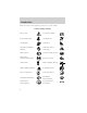
Introduction These are some of the symbols you may see on your vehicle.
Introduction Vehicle Symbol Glossary Power Window Lockout Child Safety Door Lock/Unlock Interior Luggage Compartment Release Symbol Panic Alarm Engine Oil Engine Coolant Engine Coolant Temperature Do Not Open When Hot Battery Avoid Smoking, Flames, or Sparks Battery Acid Explosive Gas Fan Warning Power Steering Fluid Maintain Correct Fluid Level MAX MIN Emission System Engine Air Filter Passenger Compartment Air Filter Jack Check fuel cap Low tire warning 9
Instrument Cluster WARNING LIGHTS AND CHIMES 4 5 60 6 3 7 2 H 0 BRAKE ! P RPMX1000 RESET TRIP A B kmiles D5 80 100 160 120 200 20 1 C 80 120 40 140 40 240 0 MPH km/h 160 F E A/B CHECK FUEL CAP Warning lights and gauges can alert you to a vehicle condition that may become serious enough to cause expensive repairs. A warning light may illuminate when a problem exists with one of your vehicle’s functions.
Instrument Cluster If the light remains on, have your vehicle serviced at the first available opportunity. Light is blinking: Engine misfire is occurring which could damage your catalytic converter. You should drive in a moderate fashion (avoid heavy acceleration and deceleration) and have your vehicle serviced at the first available opportunity.
Instrument Cluster Anti-lock brake system (ABS) To confirm the anti-lock brake system (ABS) warning light is ABS functional it will momentarily illuminate when the ignition is turned to the ON position (alternatively for some vehicles when the ignition is moved from the ON position to the START position, the light will momentarily illuminate just prior to reaching the START position). If the light remains on, continues to flash or fails to illuminate, have the ABS serviced immediately.
Instrument Cluster Engine oil pressure Illuminates when the oil pressure falls below the normal range. Check the oil level and add oil if needed. Refer to Engine oil in the Maintenance and specifications chapter. Engine coolant temperature Illuminates when the engine coolant temperature is high. Stop the vehicle as soon as safely possible, switch off the engine and let it cool. Never remove the coolant recovery cap while the engine is running or hot.
Instrument Cluster Traction ControlY active Illuminates when the Traction Controly system is active. It will be lit for a minimum of four seconds or for the duration of the Traction Controly event. For more information, refer to the Driving chapter. Steering column lock (manual transmission only) Illuminates when the steering column is locked. If this light stays illuminated the vehicle will not start, have the vehicle serviced immediately.
Instrument Cluster Bulb Warning Illuminates when one of the exterior bulbs has burned out. High beams Illuminates when the high beam headlamps are turned on. Door ajar (if equipped) Illuminates when any door or the trunk is open. Safety belt warning chime Sounds to remind you to fasten your safety belts. BeltMinderY chime Sounds intermittently to remind you to fasten your safety belts.
Instrument Cluster GAUGES 4 5 60 6 3 7 C 0 80 100 160 120 200 20 1 BRAKE ! P RPMX1000 RESET TRIP 40 2 H 80 120 140 40 240 0 MPH km/h 160 kmiles E A/B A B F CHECK FUEL CAP D5 Engine coolant temperature gauge Indicates the temperature of the engine coolant. At normal operating temperature, the needle remains within the normal area (the area between the “H” and “C”); if the needle goes above the normal range, the engine is overheating.
Instrument Cluster Fuel gauge Displays approximately how much fuel is in the fuel tank. The fuel gauge may vary slightly when the vehicle is in motion or on a grade. When refueling the vehicle from an empty indication, the amount of fuel that can be added will be less than the advertised capacity due to the reserve fuel. Speedometer Indicates the current vehicle speed. 60 80 120 40 80 100 160 120 200 20 40 140 240 0 MPH km/h 160 Odometer Registers the total kilometers (miles) of the vehicle.
Instrument Cluster Trip odometer Registers the kilometers (miles) of individual journeys. To reset, depress the control. To switch the display from Trip A to the Trip B feature, depress the A/B control. Tachometer Indicates the engine speed in revolutions per minute. Driving with your tachometer pointer continuously at the top of the scale may damage the engine.
Entertainment Systems PREMIUM AM/FM STEREO/CASSETTE BASS BAL SEL TREB FADE VOL PUSH ON CD EJ TAPE SEEK MUTE AM FM TUNE REW FF SIDE 1-2 1 2 3 RDS SCAN AUTO COMP SHUFF 5 6 4 ALPINE AUDIO SYSTEM WITH AM/FM STEREO/CASSETTE VOLUME PUSH ON BASS BAL SEL TREB CD EJ TAPE SEEK MUTE AM FM TUNE REW FF SIDE 1-2 1 2 3 4 FADE RDS DSP SCAN AUTO COMP SHUFF 5 6 Your audio system is equipped with selective lighting, a unique lighting strategy.
Entertainment Systems Volume/power control Press the control to turn the audio system on or off. VOL PUSH ON Turn the control to raise or lower volume. VOL PUSH ON If the volume is set above a certain level and the ignition is turned off, the volume will come back on at a “nominal” listening level when the ignition switch is turned back on. Speed sensitive volume With this feature, radio volume changes automatically and slightly with vehicle speed to compensate for road and wind noise.
Entertainment Systems • to increase volume compensation • to decrease or shut off the volume compensation Bass adjust The bass adjust control allows you to increase or decrease the audio system’s bass output. SEL BASS + SEL + SEL + SEL + SEL TREB Treble adjust The treble adjust control allows you to increase or decrease the audio system’s treble output. BASS TREB Speaker balance adjust Speaker sound distribution can be adjusted between the right and left speakers.
Entertainment Systems Seek function The seek function control works in radio, tape or CD mode (if equipped). Seek function in radio mode • Press to find the next listenable station down the frequency band. • Press to find the next listenable station up the frequency band. SEEK Seek function in tape mode • Press to listen to the previous selection on the tape or return to the beginning of the current selection. to listen to the next selection on the tape.
Entertainment Systems first side, direction automatically reverses to the opposite side of the tape.) To stop on a particular selection, press the control again. Scan function in CD mode (if equipped) Press the SCAN control to hear a short sampling of all selections on the CD. (The CD scans in a forward direction, wrapping back to the first track at the end of the CD.) To stop on a particular selection, press the control again.
Entertainment Systems Starting autoset memory preset 1. Select a frequency using the AM/FM select controls. 2. Press the control. 3. When the first six strong stations AUTO are filled, the station stored in memory preset control 1 will start playing. If there are less than six strong stations available on the frequency band, the remaining memory preset controls will all store the last strong station available.
Entertainment Systems Tune adjust for CD changer (if equipped) • Press to select the previous disc in the CD changer. (Play will begin on the first track of the disc unless the CD changer is in TUNE shuffle mode.) Refer to Shuffle feature for more information. Hold the control to continue reversing through the disc. to select the next disc in the CD changer. Hold the control • Press to fast-forward through the remaining discs.
Entertainment Systems Fast forward The fast forward control works in tape and CD modes (if equipped). FF • In the tape mode, tape direction 2 will automatically reverse when the end of the tape is reached. • In CD mode, pressing the control for less than three seconds results in slow forward action. Pressing the control for more than three seconds results in fast forward action. Tape direction select Press SIDE 1–2 to play the alternate side of a tape.
Entertainment Systems Shuffle feature The shuffle feature operates in CD mode and plays all tracks on the current disc in random order. If equipped with the CD changer, the shuffle feature continues to the next disc after all tracks are played. SHUFF 6 Press the SHUFFLE control to start this feature. Random order play will continue until the SHUFFLE control is pressed again.
Entertainment Systems • Use the SEL control to select the program type. With the feature on, use the SEEK or SCAN control to find the desired program type from the following selections: • Classic • Country • Info • Jazz • Oldies • R&B • Religious • Rock • Soft • Top 40 Show • With RDS activated, press the RDS control until SHOW is displayed. SEL RDS • Use the SEL control to select TYPE, NAME or NONE.
Entertainment Systems Press the control again to return to the playing media. This control will mute the playing media even if your vehicle is not equipped with a factory-installed cellular phone. Digital signal processing (if equipped) The digital signal processing (DSP) feature allows you to change the signal mode to suit your listening tastes. Press the control to turn the feature on or off. Use the SEL control to select the desired signal mode (the selected mode will appear in the display).
Entertainment Systems ALPINE AUDIOPHILE AM/FM STEREO IN-DASH SIX CD RADIO ALPINE SPORT AUDIO AM/FM STEREO IN-DASH SIX CD RADIO PREMIUM ALPINE AUDIO AM/FM STEREO IN-DASH SIX CD RADIO PREMIUM AM/FM STEREO IN DASH SIX CD RADIO 30
Entertainment Systems Volume/power control Press the control to turn the audio system on or off. Turn the control to raise or lower volume. PUSH ON If the volume is set above a certain level and the ignition is turned off, the volume will come back on at a “nominal” listening level when the ignition switch is turned back on. Bass adjust The bass adjust control allows you to increase or decrease the audio system’s bass output. Press the BASS control.
Entertainment Systems Speaker fade adjust Speaker sound can be adjusted between the front and rear speakers. Press the FADE control. Use the SEL control to adjust the sound between the front and rear speakers. Seek function The seek function works in radio or CD mode. Seek function in radio mode BAL + SEL FADE • Press to find the next listenable station down the frequency band. SEEK DOWN will display. to find the next listenable station up the frequency band. • Press SEEK UP will display.
Entertainment Systems AM/FM select The AM/FM select control works in radio and CD modes. AM FM CD AM/FM select in radio mode This control allows you to select AM or FM frequency bands. Press the control to switch between AM, FM1 or FM2 memory preset stations. AM/FM select in CD mode Press this control to stop CD play and begin radio play. Radio station memory preset The radio is equipped with six station memory preset controls.
Entertainment Systems 2. AUTOSET will flash in the display as the frequency band is scrolled through. AM FM CD 3. When the six strongest stations are filled, the station stored in memory preset control 1 will start playing. If there are fewer than six strong stations available on the frequency band, the remaining memory preset controls will all store the last strong station available. To deactivate autoset and return to your audio system’s manually set memory stations, press the AM/FM control again.
Entertainment Systems Disc adjust for CD mode • Press to select the previous DISC TUNE disc. (Play will begin on the first track of the disc unless shuffle mode is engaged.) Refer to Shuffle feature for more information. Hold the control to continue reversing through the discs. to select the next disc. Hold the control to fast-forward • Press through the remaining discs. CD select CD mode may be entered by AM CD pressing the CD control and the FM LOAD control. Load the CD into the audio system.
Entertainment Systems Load The load feature allows you to load LOAD single CDs into the player internal to the radio. This six disc CD player is equipped with a CD door. Compact discs should only be inserted into the player after the door has been opened by the player. Do not attempt to force the door open. Compact discs should only be loaded by pressing the LOAD control. Press the LOAD control. (You can choose which slot will be loaded by pressing the desired preset number.
Entertainment Systems Auto eject Press and momentarily hold the EJ EJ control to engage auto eject. All CDs which are present in the player will be ejected one at a time. If a CD is ejected and not removed from the door of the CD player, the player will automatically reload the CD. This feature may be used when the ignition is ON or OFF. Rewind The rewind control works in CD REW FF modes. Press and hold the REW control until the desired selection is reached.
Entertainment Systems Compression feature (if equipped) The compression feature operates in CD mode and brings soft and loud CD passages together for a more consistent listening level. MENU + SEL On Audiophile audios, press the MENU control until compression status is displayed. Press the SEL control to enable the compression feature when COMP OFF is displayed. Press the SEL control again to disable the feature when COMP ON is displayed.
Entertainment Systems TRAFFIC ON/OFF— Traffic announcements can be programmed as local or distant. Refer to Traffic announcements. RDS ON/OFF— This feature allows your audio system to receive text information from RDS-equipped FM radio stations. Refer to Radio Data System feature. FIND type — Allows you to select your desired FM program type and search for that selection. SHOW — Allows you to select from NAME (displays the name of the radio station), TYPE (displays the RDS program type: rock, jazz, etc.
Entertainment Systems Program type This feature allows you to search for RDS stations selectively by their program type. Press the MENU control until FIND program type is displayed. MENU + SEL Use the SEL control to select the program type.
Entertainment Systems Press the DSP control to access one of the following modes: • DSP OFF • SIGNAL MODE • OCCUPANCY MODE Use the SEL control to select the DSP + SEL SEL desired signal mode (the selected mode will appear in the display).
Entertainment Systems This control will mute the playing media even if your vehicle is not equipped with a factory-installed cellular phone. Press the control again to return to the playing media. CD CHANGER (IF EQUIPPED) The CD changer is located in the glove compartment. Press to eject the magazine. 1. Pull the lever to remove a CD tray from the magazine. 2. Insert one disc into each CD tray of the magazine (up to 6 discs). Ensure that the label side is facing up.
Entertainment Systems 3. Insert each CD tray, with the disc loaded, all the way into the CD magazine. 4. Insert the CD magazine into the changer. Use only compact discs containing this mark. Ensure that the disc is inserted label side up. The magazine does not need to be full for the changer to operate. Radio power must be turned on to play the CDs in the changer. The magazine may be stored in the glove compartment when not being used. The CD magazine may be inserted or ejected with the radio power off.
Entertainment Systems If • • • • your changer does not work, it may be that: A disc is already loaded where you want to insert a disc. The disc is inserted with the label surface downward. The disc is dusty or defective. The player’s internal temperature is above 60°C (140°F). Allow the player to cool down before operating. • A disc with format and dimensions not within industry standards is inserted. CLEANING COMPACT DISCS Inspect all discs for contamination before playing.
Entertainment Systems • Tighten very loose tapes by inserting a finger or pencil into the hole and turning the hub. • Remove loose labels before inserting tapes. • Do not leave tapes in the cassette player for a long time when not being played. RADIO FREQUENCY INFORMATION The Federal Communications Commission (FCC) and the Canadian Radio and Telecommunications Commission(CRTC) establish the frequencies AM and FM stations may use for their broadcasts.
Climate Controls DUAL AUTOMATIC TEMPERATURE CONTROL (DATC) SYSTEM EXT A/C F F F C AUTO R OFF The Dual Automatic Temperature Control (DATC) system will maintain a selected temperature and automatically control air flow. You can override the automatic operation with any of the override controls. The dual temperature zone feature allows the driver and front passenger to set their own independent temperature set points for individual comfort.
Climate Controls Turning the system off Press OFF. The outside temperature (EXT) function (if selected) will continue to operate until the ignition is turned off. EXT FC AUTO OFF DATC automatic operation Press AUTO and select the desired EXT temperature. The selected temperature will appear in the FC display window, and an indicator above the AUTO control will light. The DATC system will either heat or cool the vehicle to achieve the AUTO OFF selected temperature.
Climate Controls DATC system AUTO temperature balance EXT A/C F F F C AUTO R OFF Press and hold the AUTO control for about two seconds to equalize the passenger set temperature with the driver side temperature. This feature is useful when the driver is alone in the vehicle. Driver side temperature selection EXT A/C F F F C AUTO OFF R The display window indicates the selected temperature and manual ) if automatic fan speed is not desired.
Climate Controls maximum heating (disregarding the displayed temperature) until a cooler temperature is selected by pressing the temperature control. If maximum heating is selected, the passenger set point is not displayed and the passenger temperature adjustments will be disabled. A change of the driver-selected temperature to a temperature other than 16° C (60° F) or 32° C (90° F) will display the passenger set point.
Climate Controls Fan speed ( ) EXT A/C F F F C AUTO R OFF When AUTO is pressed, fan speed is adjusted automatically for existing conditions. You can override fan speed at any time. To control fan speed manually, press the fan control to cancel the automatic fan speed operation. Press the control up for higher fan speed or down for lower fan speed. The display will show and a bar graph to indicate manual fan speed operation and relative speed.
Climate Controls In defrost mode, if the outside temperature is about 2° C (35° F) or higher, the air conditioner will automatically dehumidify the air to reduce window fogging. However, the A/C indicator will be off and the A/C override control cannot be selected. When AUTO is selected, the A/C operates automatically for existing conditions. With automatic A/C operation, the A/C indicator will be lit if the outside temperature is about 2° C (35° F) or higher.
Climate Controls recirculated air operation and cancel automatic recirculated air operation, press the recirculated air control. When the recirculated air is manually controlled in the AUTO mode, the AUTO indicator light will remain lit. To return to full automatic recirculated air operation, press AUTO.
Climate Controls added customer comfort, the air distributed through the floor ducts may be slightly warmer than the air sent to the instrument panel registers. (floor) — Distributes air through the front and rear seat floor ducts. The system will allow some airflow out the defroster ducts, the demister outlets and outer instrument panel registers. (floor/defrost) — Distributes air through the windshield defroster ducts, the demister outlets and the front and rear seat floor ducts.
Climate Controls In cold, dry conditions where wet snow or ice is not present it is acceptable to manually deselect the operation of this feature. The feature will run continuously unless a low battery condition is detected, or unless the feature is manually deselected, and will only activate when the vehicle engine is running (to prevent excessive drain of the vehicle battery). R (rear window defroster) — Refer to Rear Window Defroster.
Climate Controls • To prevent humidity buildup inside the vehicle, don’t drive with the climate control system in the OFF position. • DO NOT leave the DATC system in recirculated air mode for extended periods of time while the system is in a heating mode or in cold or damp conditions as this may cause interior fogging of the front, side and rear windows. • Do not place objects under the front seat that will interfere with the airflow to the rear seats.
Climate Controls 4 5 60 6 3 7 C 0 80 100 160 120 200 20 1 BRAKE ! P RPMX1000 RESET TRIP 40 2 H 80 120 140 40 240 0 MPH km/h 160 F E A/B A B kmiles D 5 • Do not place items over the climate temperature sensor grid. This may cause improper operation of the DATC system. • With the ignition in the OFF position after operating the vehicle, some vehicle sounds related to the climate control system may be heard.
Climate Controls REAR WINDOW DEFROSTER Press the rear window defroster control to clear the rear window and R sideview mirrors of thin ice or fog. The indicator will illuminate when the rear window defroster is selected. The ignition must be in the RUN position and the engine running in order to operate the rear window defroster. The rear window defroster turns off automatically after 10 minutes or sooner if a low battery condition is detected, or when the ignition is turned to the OFF position.
Lights HEADLAMP CONTROL Rotate the headlamp control to the first position to turn on the parking lamps. Rotate to the second position to turn on the headlamps. AUTO Autolamp control The autolamp system provides light sensitive automatic on-off control of AUTO the exterior lights normally controlled by the headlamp control. The autolamp system also keeps the lights on for a preselected period of time after the ignition switch is turned to OFF. • To turn autolamps on, rotate the control counterclockwise.
Lights Daytime running lamps (DRL) (if equipped) Turns the highbeam headlamps on with a reduced output. To activate with automatic transmission: • the ignition must be in the RUN position; • the headlamp control is in the OFF position, Parking lamps position, or Autolamp position when the autolamp function has not turned on the headlamps (daytime); and • the transmission is out of Park.
Lights Flash to pass Pull toward you slightly to activate and release to deactivate. INT OFF INT AUTO PANEL DIMMER CONTROL Use to adjust the brightness of the instrument panel during parklamp, headlamp, and autolamp operation. • Rotate up to brighten. • Rotate down to dim. • Rotate fully up to turn on the interior lights. AIMING THE HEADLAMPS Your vehicle is equipped with a Vehicle Headlamp Aim Device (VHAD) on each headlamp body.
IN Horizontal aim adjustment 1. Park the vehicle on a level surface. 2. With the hood open, remove the protective cover, then locate the horizontal indicator and the adjusting screw. 3. Use a 4 mm wrench or socket to turn the horizontal adjusting screw until the end of the shaft within the clear tube lines up with the “0” reference mark on the indicator when viewed directly from above.
Lights Vertical aim adjustment 1. Park the vehicle on a level surface. 2. With the hood open, remove protective cover, then locate the bubble level and the vertical adjustment screw. 3. The numbers shown on the vial indicate the directional change (up or down) of the vertical aim. 4. Use a 4 mm wrench or socket to turn the vertical adjusting screw until the bubble is below the “0” mark position when viewed directly from above. 5. Install protective cover.
Lights INTERIOR LAMPS Map lamps (if equipped) The map lamps and controls are located on the dome lamp. Press the controls in front of each map lamp to activate the lamps. Rear dome lamp The dome lamp lights when: • any door is opened. • the instrument panel dimmer switch is rotated up until the courtesy lamps come on. • the remote entry UNLOCK control is pressed and the ignition is OFF.
Lights Do not remove lamp bulbs unless they will be replaced immediately. If a bulb is removed for an extended period of time, contaminants may enter the lamp housings and affect performance. Using the right bulbs Replacement bulbs are specified in the chart below. Headlamp bulbs must be marked with an authorized “D.O.T.” for North America and an “E” for Europe to assure lamp performance, light brightness and pattern and safe visibility.
Lights Interior bulbs Check the operation of the following interior bulbs frequently: • front map lamps • Rear dome/reading lamp For bulb replacement, see a dealer or qualified technician. Map lamps For bulb replacement, see a qualified service technician or your dealer. Replacing headlamp bulbs To remove the high or low beam headlamp bulb: 1. Make sure headlamp switch is in OFF position. 2. Lift the hood, push and release four tabs and remove the protective cover from the headlamps. 3.
Lights Replacing foglamp bulbs The halogen bulb contains gas under pressure. The bulb may shatter if the glass envelope is scratched or if the bulb is dropped. Handle the bulb carefully. Grasp the bulb only by its base. Avoid touching the glass envelope. 1. Disconnect the electrical connector from the foglamp bulb. 2. Rotate the foglamp bulb counterclockwise and remove from the foglamp (the rear side of the foglamp is shown). 3. Install the foglamp bulb in foglamp by rotating clockwise. 4.
Driver Controls WINDSHIELD WIPER/WASHER CONTROLS Rotate the windshield wiper control to the desired interval, low or high speed position. The ignition must be in the ACC or RUN position to operate the windshield wiper. The bars of varying length are for intermittent wipers. When in this position rotate the control upward for fast intervals and downward for slow intervals. Push the control on the end of the stalk to activate washer. Push and hold for a longer wash cycle.
Driver Controls Windshield wiper blades Check the wiper blades at least twice a year or when they seem less effective. Substances such as tree sap and some hot wax treatments used by commercial car washes reduce the effectiveness of wiper blades. In cold weather conditions, the wiper blades need to be thawed before operating in order to prevent premature wear to the wiper blades. Before operating the wiper blades in cold weather, refer to the Electric window heaters in this chapter.
Driver Controls 4. Attach the new wiper to the wiper arm and reposition the clip until it locks. Repeat for driver’s side wiper arm. TILT/TELESCOPE STEERING COLUMN Power tilt/telescope steering column Never adjust the steering wheel when the vehicle is moving. The steering column can be adjusted manually by moving the four-way rocker adjustment control located on the multi-function control below the turn signal/wiper control stalk.
Driver Controls ILLUMINATED VISOR MIRROR To turn on the visor mirror lamps, lift the mirror cover. Adjust the amount of light by sliding the control. POWER WINDOWS Press and pull the rocker switches to open and close windows. • Press the top portion of the rocker switch to open. AUTO • Pull the top portion of the rocker switch to close.
Driver Controls Express down To make the driver window open fully without holding the window control, press the top portion of the driver window control completely down to the second detent. Press or pull the control to stop window operation. Window lock The window lock feature allows only the driver to operate the rear power windows. To lock out the rear window controls press the left side of the control. Press the right side to restore the window controls.
Driver Controls Ensure the mirror is pulled down low enough to prevent visibility interference with the overhead console. The mirror support arm has two pivot points which lets you adjust the mirror UP or DOWN and from SIDE to SIDE. Press the control to turn the mirror on or off. COMP MIRROR The mirror will automatically return to the normal state whenever the vehicle is placed in R (Reverse)(when the mirror is on) to ensure a bright clear view when backing up.
Driver Controls Compass zone adjustment 1. Determine which compass zone you are in by referring to the zone map. 2. Turn the ignition to the ON/RUN position. 3. With the compass display turned on, press and hold the COMP side of the control for no more than six seconds until the zone selection number appears in the mirror display window. If a “C” appears repeat this step. 4. Release the COMP side of the control, then press it down again. NW COMP MIRROR 5.
Driver Controls Power side view mirrors The power mirrors can be operated at any time. To adjust your mirrors: 1. Select L to adjust the left mirror or R to adjust the right mirror. L R L R 2. Move the control in the direction you wish to tilt the mirror. 3. Return to the center position to lock mirrors in place. Heated outside mirrors R Both mirrors are heated automatically to remove ice, mist and fog when the rear window defrost is activated.
Driver Controls SPEED CONTROL To turn speed control on • Press ON. Vehicle speed cannot be controlled until the vehicle is traveling at or above 48 km/h (30 mph). Do not shift the gearshift lever into N (Neutral) with the speed control on. RESUME O N SET O F F Do not use the speed control in heavy traffic or on roads that are winding, slippery, or unpaved. CANCEL To turn speed control off • Press OFF or • Turn off the vehicle ignition.
Driver Controls To set a speed • Press SET+ / SET−. For speed control to operate, the speed control must be ON and the vehicle speed must be greater than 48 km/h (30 mph). RESUME O N SET O F F CANCEL If you drive up or down a steep hill, your vehicle speed may vary momentarily slower or faster than the set speed. This is normal. Speed control cannot reduce the vehicle speed if it increases above the set speed on a downhill.
Driver Controls To set a higher set speed • Press and hold SET+. Release the control when the desired vehicle speed is reached or • Press and release SET + to operate the Tap-Up function. Each press will increase the set speed by 1.6 km/h (1 mph) or • Accelerate with your accelerator pedal. When the desired vehicle speed is reached, press and release SET +. You can accelerate with the accelerator pedal at any time during speed control usage.
Driver Controls • Press CANCEL or depress the brake pedal. When the desired vehicle speed is reached, press SET + / SET −.
Driver Controls • depress the brake pedal, or • depress the clutch pedal (if equipped). Disengaging the speed control will not erase the previously programmed set speed. Pressing OFF will erase the previously programmed set speed.
Driver Controls To return to a previously set speed • Press RESUME. For RESUME to operate, the vehicle speed must be faster than 48 km/h (30 mph). RESUME O N SET O F F CANCEL Indicator light This light comes on when the vehicle speed control is engaged and actively controlling vehicle speed. STEERING WHEEL CONTROLS These controls allow you to operate some audio control features. Audio control features Press MEDIA to select AM, FM1, FM2, TAPE, or CD (if equipped).
Driver Controls In AM, FM1, or FM2 mode: • Press D or ¹ to select preset stations within the selected radio band. In Tape mode: • Press D or ¹ to select the next selection on the tape. In CD mode: • Press D or ¹ to select the next selection on the CD. In any mode: • Press VOL + or − to adjust volume. MUTE VOL MEDIA MUTE VOL MEDIA Press the PHONE/MUTE control to mute the playing media. Press again to return to the playing media.
Driver Controls MOON ROOF (IF EQUIPPED) To open the moon roof: • Push up on the control to raise the moon roof to the vent position (when the glass panel is closed). • Push the front portion of the control rearward to open the moon roof. • Press the rear portion of the control past the first detent to activate the Auto Open feature. To close the moon roof: • To close from the vent, intermediate and full open positions, push the rear portion of the control forward.
Driver Controls purchase). It is also suggested that upon the sale of the vehicle, the programmed Homelinkt Universal Transceiver buttons be erased for security purposes, refer to Programming in this section. Programming Do not program the HomeLinkt Universal Transceiver with the vehicle parked in the garage. Note: Your vehicle may require the ignition switch to be turned to the ACC position for programming and/or operation of the HomeLinkt.
Driver Controls device should activate when the HomeLinkt button is pressed and released. Note: To program the remaining two HomeLinkt buttons, begin with step 2 in the “Programming” section — do not repeat step 1. If the red light blinks rapidly for two seconds and then turns to a continuous red, proceed with steps 6 through 8 to complete programming of a rolling code equipped device. 6.
Driver Controls • Proceed with step 4 in the “Programming” section. Operating the HomeLinkT Universal Transceiver To operate, simply press and release the appropriate HomeLinkt button. Activation will now occur for the trained product (garage door, gate operator, security system, entry door lock, or home or office lighting etc.). For convenience, the hand-held transmitter of the device may also be used at any time. In the event that there are still programming difficulties, contact Homelinkt at www.
Driver Controls CELL PHONE WARNING Use of cell phones and other devices by driver: Do not operate hand held communication equipment while operating the vehicle as this may lead to an accident caused by distraction and result in personal injury. VEHICLE COMMUNICATION SYSTEM (IF EQUIPPED) The Vehicle Communication System is designed to provide a variety of safety enhancing services and offers SOS i access to hands-free calling through the Vehicle Communication System wireless phone.
Driver Controls vehicle and dispatch assistance if needed. Once a connection is made to the Lincoln Response Center, only the response center representative will be able to disconnect the call. Vehicle Communication System will redial for roadside assistance 3 times before showing on the audio display “CALL FAILED” because of network capacity or lack of analog coverage. 2.
Driver Controls “1” for activations. When calling Sprint PCS to activate your phone, please do not call from your new wireless phone. Note: Following the three-month introductory period, you must continue to enroll in a Sprint PCS voice plan in order to enable any of the Vehicle Communication System features. • Turn the ignition to “ACC”. Open the center console armrest and fold the presenter arm out. Place the wireless phone in the docking station.
Driver Controls • The wireless phone must have an active wireless service plan with Sprint PCS and docked in the docking station located in the center console for Vehicle Communication System to function properly • The vehicle must be running or the ignition must be turned to either “ACC” or “RUN/ON” position • May become inoperative if the vehicle is involved in an accident, damaging one or more components • Sprint PCS Voice Command (SM) services are only available on the Sprint PCS network Global Position
Driver Controls a brief indicator chime will sound. The system will also notify you of potential vehicle problems with a system warnings display followed by a long indicator chime. Operator selectable features These features are controlled by the message center controls located above the radio.
Driver Controls • washer fluid level • doors closed (driver and passenger side, front and rear). This message can only be reset by closing the door(s). If the RESET control is pressed, PLEASE CLOSE DOOR will be displayed.
Driver Controls Checking your highway fuel economy using the electronic message center display The following procedure will allow you to accurately monitor your actual highway fuel economy. Since this procedure requires the vehicle speed control system to be set to highway speeds, it must be run only on suitable roadways where long distance speed control can be safely maintained.
Driver Controls 2. Pressing the RESET control cycles the message center through each of the language choices. 3. Press and hold the RESET control to set the language choice. Units (English/Metric) 1. Select this function from the SETUP control for the current units to be displayed. 2. Press the RESET control to change from English to Metric. Autolocks 1. Select this function from the SETUP control for the current display mode. 2. Press the RESET control to turn the autolocks ON or OFF.
Driver Controls System warnings System warnings alert you to possible problems or malfunctions in your vehicle’s operating systems. In the event of a multiple warning situation, the message center will cycle the display to show all warnings by displaying each one for 4 seconds. The message center will display the last selected feature if there are no more warning messages.
Driver Controls Warnings Low brake fluid level Check tail lamps Check brake lamps Check front turn lamps Check side repeater lamps (if equipped) Check rear turn lamps Check Traction Control (if equipped) Check AdvanceTrac (if equipped) Trunk ajar Low washer fluid Check AC (cabin) filter Change oil soon Oil change required Data error Status Warning returns after the ignition key is turned from OFF to RUN ENGINE POWER REDUCED. Displayed when the engine is overheating.
Driver Controls Engine coolant in the Maintenance and specifications chapter. If the warning stays on or continues to come on, contact your dealer as soon as possible. CHECK CHARGING SYSTEM. Displayed when the electrical system is not maintaining proper voltage. If you are operating electrical accessories when the engine is idling at a low speed, turn off as many of the electrical loads as soon as possible.
Driver Controls CHECK REAR TURN LAMPS. Displayed when the turn signals are activated and at least one is burned out. Check the lamps as soon as possible and have the burned out lamp replaced. CHECK TRACTION CONTROL (if equipped). Displayed when the Traction Controly system is not operating properly. If this message is displayed on the message center and the amber T/C OFF light in the Traction Controly on/off switch is not illuminated, the Traction Controly system will be partially operable.
Driver Controls 3. After a successful reset, the message center will display A/C FILTER LIFE SET TO 100%. CHANGE OIL SOON/OIL CHANGE REQUIRED. Displayed when the engine oil life remaining is 5 percent or less. When oil life left is between 5% and 0%, the CHANGE OIL SOON message will be displayed. When oil life left reaches 0%, the OIL CHANGE REQUIRED message will be displayed. An oil change is required whenever indicated by the message center. USE ONLY RECOMMENDED ENGINE OILS.
Driver Controls 2. Press RESET and SETUP controls at the same time to activate a service mode which will display OIL LIFE XX% RESET TO ALTER. 3. Press RESET until you find your personalized OIL LIFE XX%. DATA ERROR. These messages indicate improper operation of the vehicle network communication between electronic modules.
Driver Controls FUEL DOOR RELEASE Press the remote fuel door release control on the instrument panel to open the fuel door. The fuel door has a manual override release located in the trunk. Pull the tab to open the fuel door. REMOVAL/INSTALLATION OF ASHTRAY Before removing and installing the ashtray, make sure the ignition is in the off position, and move the floor mounted automatic shifter from the park position. In order to prevent damage, follow these instructions when removing/installing the ashtray.
Driver Controls 3. Pull out ashtray assembly. Installation: 1. Insert ashtray into opening with face tilted upward. 2. Push face down until it clicks into position. STEERING COLUMN LOCK (IF EQUIPPED) The steering column will automatically lock when the key is removed from the ignition. When the vehicle key is inserted into the ignition, the steering column will automatically unlock. The steering column lock is equipped on manual transmission vehicles only.
Driver Controls POSITIVE RETENTION FLOOR MAT Position the floor mat so that the eyelet is over the pointed end of the retention post and rotate forward to lock in. Make sure that the mat does not interfere with the operation of the accelerator or the brake pedal. To remove the floor mat, reverse the installation procedure. CARGO NET (IF EQUIPPED) The cargo net secures lightweight objects in the cargo area. This net is not designed to restrain objects during a collision.
Locks and Security KEYS The vehicle is equipped with two master keys and a valet key lock system. The master key will access the driver’s door, trunk, glove box and ignition. The valet key will access door and ignition only. Refer to the Securilock Passive Anti-Theft System section for information on Securilock keys. POWER DOOR LOCKS Press the top of the control to unlock all doors and the bottom to lock all doors. When the vehicle is armed the power door locks and remote trunk release control are disabled.
Locks and Security Childproof door locks When these locks are set, the rear doors cannot be opened from the inside. The rear doors can be opened from the outside when the doors are unlocked. The childproof locks are located on rear edge of each rear door and must be set separately for each door. Setting the lock for one door will not automatically set the lock for both doors. Rotate lock control in the direction of arrow to engage the lock.
Locks and Security Keep vehicle doors and luggage compartment locked and keep keys and remote transmitters out of a child’s reach. Unsupervised children could lock themselves in an open trunk and risk injury. Children should be taught not to play in vehicles. On hot days, the temperature in the trunk or vehicle interior can rise very quickly. Exposure of people or animals to these high temperatures for even a short time can cause death or serious heat-related injuries, including brain damage.
Locks and Security • operate the memory seat/mirror/steering column feature (if equipped). The remote transmitter features only operate with the ignition in the OFF or ACC positions. For vehicles equipped with an automatic transmission, the remote transmitter features also operate if the ignition is in the RUN position and the gear shift is in P (Park). The personal alarm feature, however, will not operate when the ignition is in the RUN position.
Locks and Security Opening all windows and moonroof (if equipped) Press this control and hold down for more than one second to begin to open all the windows and moonroof. Release the control to stop. If the control is held down for more than four seconds, the windows and moonroof will open fully. Locking the doors Press this control to lock all the doors and arm the perimeter anti-theft system (also enables the ignition tamper security system).
Locks and Security Activating the personal alarm Press this control to turn on the personal alarm. Press the control a second time to turn off the personal alarm. The personal alarm will also turn off if the remote transmitter unlock control is pressed, or if the ignition switch is turned to the RUN position, or after 30 seconds of operation. Opening the trunk Press this control to open the trunk. Be certain the trunk is closed before driving your vehicle.
Locks and Security To replace the battery: 1. Twist a thin coin between the two halves of the transmitter near the key ring. DO NOT TAKE THE FRONT PART OF THE TRANSMITTER APART. 2. Place the positive (+) side of new battery in the same orientation. Refer to the diagram inside the transmitter unit. 3. Snap the two halves back together. Replacement of the battery will not cause the remote transmitter to become deprogrammed from your vehicle.
Locks and Security The battery saver will turn off the interior lamps 40 minutes after the last door is closed even if the dimmer control switch is on. Autolock/Relock This feature automatically locks all vehicle doors when: • all doors are closed, and • the engine is running, and • you shift into any gear putting the vehicle in motion. Relock The autolock feature repeats when: • any door is opened then closed while the engine is running, and • you put the vehicle in motion.
Locks and Security 4. Repeat this procedure for another remote transmitter if desired. Deactivating the stored memory seat/mirror/steering column positions To deactivate this feature: 1. Press the SET control on the driver’s door panel. 2. Within 5 five seconds, press one control on the remote transmitter which you would like to deactivate and then press the SET control on the driver’s door panel. 3. Repeat this procedure for another remote transmitter if desired.
Locks and Security Automatic arming The vehicle is armed immediately after switching the ignition to the 2 (OFF) position. 2 1 3 4 5 Automatic disarming Switching the ignition to the 4 (RUN) position with a coded key disarms the vehicle. The indicator light on the instrument panel will illuminate for three seconds and then go out. If the light stays on for an extended period of time or flashes rapidly, have the system serviced by your dealership or a qualified technician.
Locks and Security Replacing coded keys can be very costly and you may want to store an extra programmed key away from the vehicle in a safe place to prevent an unforeseen inconvenience. The correct coded key must be used for your vehicle. The use of the wrong type of coded key may lead to a “no start” condition. If an unprogrammed key is used in the ignition it will cause a “no start” condition. Programming spare keys A maximum of eight keys can be coded to your vehicle. Only SecuriLocky keys can be used.
Locks and Security If successful, the new coded key(s) will start the vehicle’s engine and the theft indicator will illuminate for three seconds and then go out. If not successful, the new coded key(s) will not start the vehicle’s engine and the theft indicator will flash on and off and you may repeat steps 1 through 6. If failure repeats, bring your vehicle to your dealership to have the new spare key(s) programmed.
Seating and Safety Restraints SEATING Adjustable head restraints (if equipped) Your vehicle’s seats may be equipped with head restraints which are vertically adjustable. The purpose of these head restraints is to help limit head motion in the event of a rear collision. To properly adjust your head restraints, lift the head restraint so that it is located directly behind your head or as close to that position as possible. Refer to the following to raise and lower the head restraints.
Seating and Safety Restraints The head restraints can be moved in four directions and use the same release control as the two-way head restraints: • up and down • forward or backward Using the manual lumbar support (if equipped) The lumbar control is located on the front of the seat cushion. Turn to adjust lumbar support. Using the power lumbar support (if equipped) The power lumbar control is located on the outboard side of the seat. Press one side of the control to adjust firmness.
Seating and Safety Restraints Heated seats (if equipped) To operate the heated seats: • Push control to activate. • Push again to deactivate. The heated seats will activate when the ignition is in the RUN position. When activated, they will turn off automatically after 10 minutes or when the ignition is turned to the OFF position. The indicator light will illuminate when the heated seats have been activated. Adjusting the power seats The power seat controls are located on the outboard side of the seat.
Seating and Safety Restraints Rotate the vertical control to adjust the seatback. • 8 way • 6 way Slide the control forward or backward to move the seat forward or backward. • 8 way • 6 way Move the control up or down to move the seat up and down. • 8 way • 6 way Move front/rear of control up/down to tilt seat cushion.
Seating and Safety Restraints The seat will move 5 cm (2 inches) forward (to the original position) when: • the transmission is in N (Neutral) or P (Park) • the key is placed in the ignition cylinder Deactivating/activating the easy access/easy out feature The easy access/easy out feature can be turned off or on through the vehicle message center (if equipped). If your vehicle does not have a message center, the feature can be turned off or on by your dealer.
Seating and Safety Restraints 2ND SEAT/SPLIT-FOLDING REAR SEAT One or both rear seatbacks can be folded down to provide additional cargo space. To lower the seatback(s), pull the release handle(s) located inside the trunk. Fold the seatback(s) down. When raising the seatback(s), make sure you hear the seat latch into place. Make sure that the safety belt for the rear center passenger is properly routed over the rear seatback.
Seating and Safety Restraints Never let a passenger hold a child on his or her lap while the vehicle is moving. The passenger cannot protect the child from injury in a collision. All occupants of the vehicle, including the driver, should always properly wear their safety belts, even when an air bag (SRS) is provided. It is extremely dangerous to ride in a cargo area, inside or outside of a vehicle. In a collision, people riding in these areas are more likely to be seriously injured or killed.
Seating and Safety Restraints Combination lap and shoulder belts • Front seat belts • Rear seat belts 122
Seating and Safety Restraints 1. Insert the belt tongue into the proper buckle (the buckle closest to the direction the tongue is coming from) until you hear a snap and feel it latch. Make sure the tongue is securely fastened in the buckle. 2. To unfasten, push the release button and remove the tongue from the buckle.
Seating and Safety Restraints Failure to replace the belt and retractor assembly could increase the risk of injury in collisions. The front outboard and rear safety restraints in the vehicle are combination lap and shoulder belts. The front passenger and rear seat safety belts have two types of locking modes. Vehicle sensitive mode The vehicle sensitive mode is the normal retractor mode, allowing free shoulder belt length adjustment to your movements and locking in response to vehicle movement.
Seating and Safety Restraints • Grasp the shoulder portion and pull downward until the entire belt is extracted. • Allow the belt to retract. As the belt retracts, you will hear a clicking sound. This indicates the safety belt is now in the automatic locking mode. In this mode, the shoulder belt is automatically pre-locked. The belt will still retract to remove any slack in the shoulder belt. The automatic locking mode is not available on the driver safety belt.
Seating and Safety Restraints Safety belt pretensioner Your vehicle is equipped with safety belt pretensioners at the driver and front passenger seating positions. The safety belt pretensioner is a device which removes excess webbing from the safety belt system. The safety belt pretensioner uses the same crash sensor system as the front air bag supplemental restraint system (SRS). When the safety belt pretensioner deploys, webbing from the lap and shoulder belt is tightened.
Seating and Safety Restraints Safety belt warning light and indicator chime The seat belt warning light illuminates in the instrument cluster and a chime sounds to remind the occupants to fasten their safety belts. Conditions of operation If... The driver’s safety belt is not buckled before the ignition switch is turned to the RUN position... Then... The safety belt warning light illuminates 1-2 minutes and the warning chime sounds 4-8 seconds. The safety belt warning light and warning chime turn off.
Seating and Safety Restraints If... Then... The driver’s safety belt is buckled The BeltMinder feature will not before the ignition switch is turned activate. to the ON position... The purpose of the BeltMinder is to remind occasional wearers to wear safety belts all of the time. The following are reasons most often given for not wearing safety belts: (All statistics based on U.S. data) Reasons given... “Crashes are rare events” Consider... 36 700 crashes occur every day.
Seating and Safety Restraints Reasons given... Consider... “I have an air bag” Air bags offer greater protection when used with safety belts. Frontal airbags are not designed to inflate in rear and side crashes or rollovers. “I’d rather be Not a good idea. People who are ejected are 40 thrown clear” times more likely to DIE. Safety belts help prevent ejection, WE CAN’T “PICK OUR CRASH”. Do not sit on top of a buckled safety belt to avoid the Belt Minder chime.
Seating and Safety Restraints • Steps 3–5 must be completed within 60 seconds or the procedure will have to be repeated. 3. Buckle then unbuckle the safety belt three times, ending with the safety belt unbuckled. This can be done before or during BeltMinder warning activation. 4. Turn on the parklamps, turn off the parklamps. 5. Buckle then unbuckle the safety belt three times, ending with the safety belt unbuckled. • After step 5 the safety belt warning light will be turned on for three seconds. 6.
Seating and Safety Restraints there are no nicks, tears or cuts. Replace if necessary. All safety belt assemblies, including retractors, buckles, front seat belt buckle assemblies, buckle support assemblies (slide bar-if equipped), shoulder belt height adjusters (if equipped), shoulder belt guide on seatback (if equipped), child safety seat tether bracket assemblies (if equipped), LATCH child seat tether anchors and lower anchors (if equipped), and attaching hardware, should be inspected after a collision.
Seating and Safety Restraints Important supplemental restraint system (SRS) precautions The supplemental restraint system is designed to work with the safety belt to help protect the driver and right front passenger from certain upper body injuries. Air bags DO NOT inflate slowly or gently and the risk of injury from a deploying air bag is greatest close to the trim covering the air bag module.
Seating and Safety Restraints Do not attempt to service, repair, or modify the air bag supplemental restraint systems or its fuses. See your Ford or Lincoln Mercury dealer. Modifications to the front end of the vehicle, including frame, bumper, front end body structure and tow hooks may affect the performance of the air bag sensors increasing the risk of injury. Do not modify the front end of the vehicle.
Seating and Safety Restraints How does the safety belt pretensioner and air bag supplemental restraint system work? The safety belt pretensioner and air bag SRS are designed to activate when the vehicle sustains longitudinal deceleration sufficient to cause the sensors to close an electrical circuit that initiates pretensioner activation and air bag inflation. The fact that the pretensioners and air bags did not activate in a collision does not mean that something is wrong with the system.
Seating and Safety Restraints are not properly restrained or are otherwise out of position at the time of air bag deployment. Thus, it is extremely important that occupants be properly restrained as far away from the air bag module as possible while maintaining vehicle control. Several air bag system components get hot after inflation. Do not touch them after inflation. If the air bag has deployed, the air bag will not function again and must be replaced immediately.
Seating and Safety Restraints Any difficulty with the system is indicated by one or more of the following: • The readiness light will either flash or stay lit • The readiness light will not illuminate immediately after ignition is turned to the RUN position • A series of five beeps will be heard. The tone pattern will repeat periodically until the problem and/or light are repaired.
Seating and Safety Restraints How does the side air bag system work? The side air bag system consists of the following: • An inflatable nylon bag (air bag) with a gas generator concealed behind the outboard bolster of the driver and front passenger seatbacks. • A special seat cover designed to allow air bag deployment. • The same warning light, electronic control and diagnostic unit as used for the front air bags.
Seating and Safety Restraints Several air bag system components get hot after inflation. Do not touch them after inflation. If the side air bag has deployed, the air bag will not function again. The side air bag system (including the seat) must be inspected and serviced by a qualified technician in accordance with the vehicle service manual. If the air bag is not replaced, the unrepaired area will increase the risk of injury in a collision.
Seating and Safety Restraints SAFETY RESTRAINTS FOR CHILDREN See the following sections for directions on how to properly use safety restraints for children. Also see Air bag supplemental restraint system (SRS) in this chapter for special instructions about using air bags. Important child restraint precautions You are required by law to use safety restraints for children in the U.S. and Canada.
Seating and Safety Restraints Child booster seats Children outgrow a typical convertible or toddler seat when they weigh 40 pounds and are around 4 years of age. Although the lap/shoulder belt will provide some protection, these children are still too small for lap/shoulder belts to fit properly, which could increase the risk of serious injury.
Seating and Safety Restraints Types of booster seats There are two types of belt-positioning booster seats: • Those that are backless. If your backless booster seat has a removable shield, remove the shield and use the lap/shoulder belt. If a seating position has a low seat back and no head restraint, a backless booster seat may place your child’s head (top of ear level) above the top of the seat.
Seating and Safety Restraints Follow all instructions provided by the manufacturer of the booster seat. Never put the shoulder belt under a child’s arm or behind the back because it eliminates the protection for the upper part of the body and may increase the risk of injury or death in a collision. Never use pillows, books, or towels to boost a child. They can slide around and increase the likelihood of injury or death in a collision.
Seating and Safety Restraints When installing a child safety seat: • Review and follow the information presented in the Air Bag Supplemental Restraint System section in this chapter. • Use the correct safety belt buckle for that seating position. • Insert the belt tongue into the proper buckle until you hear a snap and feel it latch. Make sure the tongue is securely fastened in the buckle.
Seating and Safety Restraints 1. Position the child safety seat in a seat with a combination lap and shoulder belt. Children 12 and under should be properly restrained in the rear seat whenever possible. 2. Pull down on the shoulder belt and then grasp the shoulder belt and lap belt together. 3. While holding the shoulder and lap belt portions together, route the tongue through the child seat according to the child seat manufacturer’s instructions. Be sure the belt webbing is not twisted.
Seating and Safety Restraints 4. Insert the belt tongue into the proper buckle (the buckle closest to the direction the tongue is coming from) for that seating position until you hear a snap and feel the latch engage. Make sure the tongue is latched securely by pulling on it. 5. To put the retractor in the automatic locking mode, grasp the shoulder portion of the belt and pull downward until all of the belt is pulled out and a click is heard. 6. Allow the belt to retract.
Seating and Safety Restraints 8. Allow the safety belt to retract to remove any slack in the belt. 9. Before placing the child in the seat, forcibly tilt the seat forward and back to make sure the seat is securely held in place. To check this, grab the seat at the belt path and attempt to move it side to side and forward and back. There should be no more than one inch of movement for proper installation. 10.
Seating and Safety Restraints Attach the tether strap only to the appropriate tether anchor as shown. The tether strap may not work properly if attached somewhere other than the correct tether anchor. 1. Position the child safety seat on the seat cushion. 2. Route the child safety seat tether strap over the back of the seat.
Seating and Safety Restraints If the safety seat is not anchored properly, the risk of a child being injured in a collision greatly increases. Attaching safety seats with LATCH (Lower Anchors and Tethers for Children) attachments for child seat anchors Some child safety seats have two rigid or webbing mounted attachments that connect to two anchors at certain seating positions in your vehicle. This type of child seat eliminates the need to use seat belts to attach the child seat.
Seating and Safety Restraints The lower anchors for child seat installation are located at the rear section of the rear seat between the cushion and seat back. The LATCH anchors are below the locator symbols on the seat back. Follow the child seat manufacturer’s instructions to properly install a child seat with LATCH attachments. Two plastic LATCH guides can be obtained at no charge from any Ford or Lincoln-Mercury dealer.
Driving STARTING Positions of the ignition 1. LOCK, locks the gearshift lever (automatic transmission only) and allows key removal. 2. OFF, shuts off the engine and all accessories without locking the steering wheel (if equipped). This position also allows the automatic transmission shift lever to be moved from the P (Park) position without the brake pedal being depressed.
Driving Do not park, idle, or drive your vehicle in dry grass or other dry ground cover. The emission system heats up the engine compartment and exhaust system, which can start a fire. Do not start your vehicle in a closed garage or in other enclosed areas. Exhaust fumes can be toxic. Always open the garage door before you start the engine. See Guarding against exhaust fumes in this chapter for more instructions.
Driving • Push the clutch pedal to the floor. 3. Turn the key to 4 (RUN) without turning the key to 5 (START). 2 3 1 4 5 4 5 6 3 60 7 2 H 80 100 160 120 200 20 1 C 80 120 40 0 BRAKE ! P RPMX1000 RESET 40 140 240 0 MPH km/h 160 F E A/B CHECK FUEL CAP Make sure the corresponding lights illuminate or illuminate briefly. If a light fails to illuminate, have the vehicle serviced. • If the driver’s safety belt is fastened, the light may not illuminate.
Driving 1. Turn the key to 5 (START) without pressing the accelerator 2 pedal and release as soon as the 1 engine starts. The key will return to 4 (RUN). 2. If the temperature is above –12° C (10° F) and the engine does not start within five seconds on the first try, turn the key to OFF, wait 10 seconds and try again. 3 4 5 3. If the temperature is below -12° C (10° F) and the engine does not start in 15 seconds on the first try, turn the key OFF and wait 10 seconds and try again.
Driving If you ever smell exhaust fumes of any kind inside your vehicle, have your dealer inspect and fix your vehicle immediately. Do not drive if you smell exhaust fumes. These fumes are harmful and could kill you. Have the exhaust and body ventilation systems checked whenever: • the vehicle is raised for service. • the sound of the exhaust system changes. • the vehicle has been damaged in a collision.
Driving If you are driving down a long or steep hill, shift to a lower gear. Do not apply your brakes continuously, as they may overheat and become less effective. Anti-lock brake system (ABS) On vehicles equipped with an anti-lock braking system (ABS), a noise from the hydraulic pump motor and pulsation in the pedal may be observed during ABS braking events.
Driving ABS warning lamp ABS The ABS warning lamp in the instrument cluster momentarily illuminates when the ignition is turned to the RUN position. If the light does not illuminate momentarily at start up, remains on or continues to flash, the ABS needs to be serviced. With the ABS light on, the anti-lock BRAKE brake system is disabled and normal braking is still effective unless the ! P brake warning light also remains illuminated with parking brake released.
Driving Your brake handle may need to be pulled up slightly to release pressure before pushing in the button. Push the button on the end of the parking brake and push the handle down as far as possible to release the brake. Driving with the parking brake on will cause the brakes to wear out quickly and reduce fuel economy. STEERING Your vehicle is equipped with power steering. Power steering uses energy from the engine to decrease the driver’s effort in steering the vehicle.
Driving TRACTION CONTROLY The Traction Controly system helps maintain the stability and steerability of your vehicle. It is especially useful on slippery and/or hilly road surfaces. The system operates at all speeds by detecting and controlling wheel spin. The system borrows many of the electronic and mechanical elements already present in the anti-lock braking system (ABS). Wheel-speed sensors allow excess rear wheel spin to be detected by the Traction Controly portion of the ABS computer.
Driving AdvanceTracY Stability Enhancement System (if equipped) The AdvanceTracy system helps the driver maintain the stability and steerability of the vehicle. The system integrates anti-lock braking system (ABS), Traction Controly and a more advanced function to further enhance the stability of the vehicle. The system shares many of the electronic and mechanical elements already present in the Traction Controly and ABS systems.
Driving The AdvanceTracy on/off control button allows the driver to control the availability of the Traction Controly and AdvanceTracy OFF system. This is independent of the ABS function, which CANNOT be switched off by the driver. The AdvanceTracy system status is ATS indicated by a warning indicator light with a “sliding car” icon in the instrument cluster that will flash when the system is active and an indicator light in the control button that will illuminate when the system is turned OFF.
Driving If you find yourself regularly experiencing AdvanceTracy events, you are driving too fast for conditions, you should reduce your speed, and drive less aggressively. AdvanceTracy is limited by the laws of physics. It is always possible to lose control of a vehicle due to inappropriate driver inputs for the conditions.
Driving Do not rock the vehicle if the engine is not at normal operating temperature or damage to the transmission may occur. Do not rock the vehicle for more than a few minutes or damage to the transmission and tires may occur or the engine may overheat. Always set the parking brake fully and make sure the gearshift is latched in P (Park). Turn the ignition to the LOCK position and remove the key whenever you leave your vehicle.
Driving 3 1 2 D5 D4 R N Always set the parking brake fully and make sure the gearshift lever is latched in P (Park). Turn off the ignition whenever you leave your vehicle. P P (Park) Always come to a complete stop before shifting into P (Park). Make sure the gearshift lever is securely latched in P (Park). This position locks the transmission and prevents the rear wheels from turning. R (Reverse) D4 1 2 3 D5 N R P With the gearshift lever in R (Reverse), the vehicle will move backward.
Driving D4 3 1 2 D5 N R P N (Neutral) With the gearshift lever in N (Neutral), the vehicle can be started and is free to roll. Hold the brake pedal down while in this gear. D4 1 2 3 D5 N R P Drive 5 (Overdrive) The normal driving position for the best fuel economy. Transmission operates in gears one through five.
Driving D4 3 1 2 3 D5 D4 R N 3 (Third) Transmission operates in third gear only. Selecting 3 (Third) provides engine braking. Upshifts can be made by shifting to 4 (Drive) or 5 (Overdrive). Selecting 3 (Third) at higher speeds causes the transmission to shift to a lower gear, and will shift to 3 (Third) after vehicle decelerates to the proper speed. P 1 2 D5 N R P Drive 4 (Drive) Transmission operates in gears one through four.
3 1 2 D5 D4 R N P 1 2 3 D5 D4 R 1 (First) Use 1 (Low) to provide maximum engine braking on steep downgrades. Upshifts can be made by shifting to 2 (Second), 3 (Third), 4 (Drive) or 5 (Overdrive). Selecting 1 (Low) at higher speeds causes the transmission to shift to a lower gear, and will shift to 1 (Low) after vehicle decelerates to the proper speed. N 2 (Second) Use 2 (Second) to start-up on slippery roads or to provide additional engine braking on downgrades.
Driving transmission. Once the vehicle is at operating temperature it may take several shifts at the same operating condition for the transmission to properly adapt. Over time the adaptive learning process will fully update transmission operation. The more varied the driving habits, speed and torque, the longer it may take to adapt but the more complete the process will be. When the battery is disconnected or a new battery installed, the transmission must relearn its adaptive strategy.
Driving Automatic shift mode When in the automatic shift mode (D5 position), the 5–speed automatic transmission operates like a typical automatic transmission. Pull the gearshift lever towards you and downward to move the automatic gearshift. Refer to Driving with a 5–speed automatic transmission in this chapter for Park, Reverse, Neutral, D5 and D4 information. Manual shift mode With the gearshift lever in D5 (Overdrive), the gearshift lever can be moved to the right and into the manual shift mode.
Driving + and - position operation These positions allow the driver to manually select the appropriate upshift (+) or downshift (-) and gear range. • Can only be entered from the D5 (Overdrive) shift position. • Gear ranges 1–5 provide the same function and ratio as found in the D5 or D4 automatic mode positions. • The transmission will not upshift or downshift unless the gearshift lever is moved forward or rearward. • One tap forward (+) will command the transmission to upshift one gear range.
Driving downshift into the next lower gear to prevent possible engine and/or transmission damage. Once the vehicle reaches below a specified entry speed for the next lower gear, the transmission will allow another downshift to occur if selected by the driver. Recommended Shift Speeds Upshift according to the following charts: 1 2 3 4 1 2 3 4 1 2 3 4 170 - - - 2 3 4 5 Recommended upshifts when accelerating Select Shift V6 3.
Driving 1 2 3 4 - 2 3 4 5 Recommended upshifts when cruising Select Shift V8 3.9L Shift from: n/a 26 km/h (16 mph) 47 km/h (29 mph) 61 km/h (38 mph) MANUAL TRANSMISSION OPERATION (IF EQUIPPED) Using the clutch Vehicles equipped with a manual transmission have a starter interlock that prevents cranking the engine unless the clutch pedal is fully depressed. When starting a vehicle with a manual transmission, you must: 1. Make sure the parking brake is fully set. R 1 3 5 2. Depress the clutch pedal fully.
Driving 4. Turn the ignition to position 5 (START) to start the engine, let the engine idle for a few seconds. 5. Depress the brake pedal. 6. Release the parking brake. 7. Move the gearshift lever to the desired gear. 8. Release the brake pedal. 9. Slowly release the clutch pedal while slowly pressing down on the accelerator pedal. 2 3 1 4 5 • Do not drive with your foot resting on the clutch pedal and do not use the clutch to hold your vehicle at a standstill while waiting on a hill.
Driving 1 2 3 4 - 2 3 4 5 Recommended upshifts when cruising 5-speed manual transmission Shift from: 18 km/h (11 mph) 32 km/h (20 mph) 51 km/h (32 mph) 68 km/h (42 mph) Parking your vehicle 1. Disengage the clutch, apply brake and shift into N (Neutral). R 1 3 5 2 4 2. Set parking brake. 3. Shift into 1 (First).
Driving 4. Turn the ignition key to position 1 (LOCK). 2 1 3 4 5 Do not park your vehicle in Neutral, it may move unexpectedly and injure someone. Use 1 (First) gear and set the parking brake fully. Reverse Make sure that your vehicle is at a complete stop before you shift into R (Reverse). Failure to do so may damage the transmission. Put the gearshift lever in N (Neutral) and wait at least three seconds before shifting into R R 1 3 5 (Reverse).
Driving If driving through deep or standing water is unavoidable, proceed very slowly. Never drive through water that is higher than the bottom of the hubs (for trucks) or the bottom of the wheel rims (for cars). Once through the water, always try the brakes. Wet brakes do not stop the vehicle as effectively as dry brakes. Drying can be improved by moving your vehicle slowly while applying light pressure on the brake pedal.
Driving • Maximum Trailer Weight: Maximum weight of a trailer the loaded vehicle (including occupants and cargo) is permitted to tow. It is determined by subtracting the weight of the loaded trailer towing vehicle from the GCWR for the towing vehicle. • Trailer Weight Range: Specified weight range that the trailer must fall within that ranges from zero to the maximum trailer weight rating. Remember to figure in the tongue load of your loaded trailer when figuring the total weight.
Driving Follow these guidelines to ensure safe towing procedure: • Stay within your vehicle’s load limits. If exceeded, cargo should be removed from the trailer and/or the vehicle until all weights are within specified limits. • Thoroughly prepare your vehicle for towing. Refer to Preparing to tow in this chapter. • Use extra caution when driving while trailer towing. Refer to Driving while you tow in this chapter. • Service your vehicle more frequently if you tow a trailer.
Driving Preparing to tow Use the proper equipment for towing a trailer, and make sure it is properly attached to your vehicle. See your dealer or a reliable trailer dealer if you require assistance. Hitches Do not use hitches that clamp onto the vehicle bumper. Use a load carrying hitch. You must distribute the load in your trailer so that 10% of the total weight of the trailer is on the tongue. Safety chains Always connect the trailer’s safety chains to the frame or hook retainers of the vehicle hitch.
Driving Your vehicle is ready to install a Trailer Tow module that will provide the proper communication with the vehicle electrical system so your trailer lamps will function properly. See your dealer or trailer rental agency for proper instructions and equipment for hooking up trailer lamps. Driving while you tow When towing a trailer: • Ensure that you turn off your speed control. The speed control may shut off automatically when you are towing on long, steep grades.
Driving RECREATIONAL TOWING (ALL WHEELS ON THE GROUND) Follow these guidelines for your specific powertrain combination to tow your vehicle with all four wheels on the ground (such as behind a recreational vehicle). These guidelines are designed to ensure that your transmission is not damaged due to insufficient lubrication. All Rear Wheel Drive (RWD) vehicles This applies to all cars and 4x2 trucks/sport utilities with rear wheel drive capability.
Roadside Emergencies GETTING ROADSIDE ASSISTANCE To fully assist you should you have a vehicle concern, Ford Motor Company offers a complimentary roadside assistance program. This program is separate from the New Vehicle Limited Warranty. The service is available: • 24–hours, seven days a week • for the New Vehicle Limited Warranty period of three years or 60,000 km (36,000 miles), whichever occurs first on Ford and Mercury vehicles, and four years or 80,000 km (50,000 miles) on Lincoln vehicles.
Roadside Emergencies Canadian customers who require roadside assistance, call 1–800–665–2006. If you need to arrange roadside assistance for yourself, Ford Motor Company will reimburse a reasonable amount. To obtain reimbursement information, U.S. Ford or Mercury vehicles customers call 1-800-241-3673; Lincoln vehicle customers call 1–800–521–4140. Canadian customers who need to obtain reimbursement information, call 1–800–665–2006.
Roadside Emergencies The fuel pump shut-off switch is located in the driver’s foot well, behind the kick panel. The reset button (RED) for the fuel pump shut-off switch is accessible through an opening in the kick panel. Use the following procedure to reset the fuel pump shut-off switch. 1. Turn the ignition to the OFF position. 2. Check the fuel system for leaks. 3. If no fuel leak is apparent, reset the fuel pump shut-off switch by pushing in on the reset button. 4. Turn the ignition to the RUN position.
Roadside Emergencies Note: Always replace a fuse with one that has the specified amperage rating. Using a fuse with a higher amperage rating can cause severe wire damage and could start a fire. Standard fuse amperage rating and color COLOR Fuse rating Mini fuses Standard fuses Maxi fuses 2A 3A 4A 5A 7.
FUSE 7 FUSE 21 FUSE 35 FUSE 6 FUSE 20 FUSE 34 FUSE 5 FUSE 19 FUSE 33 FUSE 4 FUSE 18 FUSE 32 FUSE 3 FUSE 17 FUSE 31 FUSE 2 FUSE 16 FUSE 30 FUSE 1 FUSE 15 FUSE 29 FUSE 12 FUSE 26 FUSE 14 FUSE 11 FUSE 25 FUSE 28 FUSE 10 FUSE 24 FUSE 13 FUSE 9 FUSE 23 FUSE 22 FUSE 8 RELAY 1 SEE OWNER'S MANUAL FUSE 27 REPLACEMENT FUSES Roadside Emergencies The fuses are coded as follows.
Roadside Emergencies Fuse/Relay Location 9 10 Fuse Amp Rating 10A 5A 11 12 13 14 15 16 10A 5A 5A 10A 5A 5A 17 18 19 20 5A 20A 15A 10A 21 22 23 24 25 26 27 28 29 30 31 32 33 34 35 10A 10A 10A 5A 10A 10A 10A 5A 5A 5A — 20A 10A 10A 5A 186 Passenger Compartment Fuse Panel Description Right Front Low Beam Left Front Turn, Left Front Repeater, Left Front Sidemarker, Left Front Park Lamps Left Front High Beam Headlamp Leveling (if equipped) Cluster RCM, DATC Not Used (Spare) E/C Mirror, Heated Seat Contro
Roadside Emergencies Front power distribution box The front power distribution box is located in the engine compartment. The power distribution box contains high-current fuses that protect your vehicle’s main electrical systems from overloads. 7 Always disconnect the battery before servicing high current fuses. To reduce risk of electrical shock, always replace the cover to the Power Distribution Box before reconnecting the battery or refilling fluid reservoirs.
Roadside Emergencies 1 2 3 4 5 6 7 8 13 14 15 16 17 18 19 20 21 22 23 24 RELAY 05 RELAY 11 RELAY 12 RELAY 14 RELAY 15 RELAY 02 RELAY 03 RELAY 06 RELAY 07 RELAY 13 RELAY 09 RELAY 04 RELAY 08 RELAY 01 RELAY 10 DIODE 9 10 11 12 The high-current fuses are coded as follows.
Roadside Emergencies Fuse/Relay Fuse Amp Power Distribution Box Description Location Rating 14 30A** ABS Module 15 — Not Used 16 30A** Blower Motor 17 20A** Thermactor Air Pump (V6 Engines Only) 18 40A** PCM 19 — Not Used 20 30A** Wiper Motor 21 30A** Starter Solenoid 22 30A** ABS Motor 23 — Not Used (Fuse Plug) 24 — Not Used Relay 01 — Wiper Hi/Lo Relay 02 — Wiper Park Relay 03 — COPs and HEGOs Relay 04 — Not Used Relay 05 — Auxiliary Coolant Pump (V8) Relay 06 — Horn Relay 07 — Fog Lamps Relay 08 — A/C Cl
Roadside Emergencies Rear power distribution box The rear power distribution box is located in the luggage compartment under the spare tire well cover. The power distribution box contains high-current fuses that protect your vehicle’s main electrical systems from overloads. Always disconnect the battery before servicing high current fuses. To reduce risk of electrical shock, always replace the cover to the Power Distribution Box before reconnecting the battery or refilling fluid reservoirs.
Roadside Emergencies 1 2 3 4 5 6 7 8 9 19 20 21 22 23 24 25 10 11 12 13 14 15 16 17 18 26 27 28 29 30 31 32 > PBT < MINI-FUSE RELAY 001 RELAY 002 RELAY 007 CARTRIDGE FUSE RELAY 003 RELAY 004 RELAY 005 RELAY 006 DIODE 01 DIODE 02 SEE OWNER'S MANUAL CONSULTER LA GUIDE The high-current fuses are coded as follows.
Roadside Emergencies Fuse/Relay Fuse Amp Location Rating 19 20A** 20 20A** 21 20A** 22 20A** 23 30A** 24 30A** 25 40A** 26 20A** 27 30A** 28 20A** 29 30A** 30 20A** 31 20A** 32 30A** Relay 001 — Relay 002 — Relay 003 — Relay 004 — Relay 005 — Relay 006 — Relay 007 — Diode 01 — Diode 02 — *Mini fuses **Maxi fuses Power Distribution Box Description REM - Left Rear Window DDM - Driver Window Driver Lumbar, Power Seats Ignition Switch SSP4 SSP3 P-J/B FEM - Front Passenger Window SSP1 Passenger Lumbar, Power Se
Roadside Emergencies Temporary spare tire information Your vehicle may have a temporary or full-size spare tire. The temporary spare tire for your vehicle is labeled as such. It is smaller than a regular tire and is designed for emergency use only. Replace this tire with a full-size tire as soon as possible. If you use the temporary spare tire continuously or do not follow these precautions, the tire could fail, causing you to lose control of the vehicle, possibly injuring yourself or others.
Roadside Emergencies If the vehicle slips off the jack, you or someone else could be seriously injured. 1. Park on a level surface, activate hazard flashers and set parking brake. 2. Place gearshift lever in P (Park) or R (manual transmission), turn engine OFF, and block the diagonally opposite wheel. 3. Lift the trunk cargo cover and remove the spare tire, jack and lug wrench.
Roadside Emergencies 4. Loosen each wheel lug nut one-half turn counterclockwise but do not remove them until the wheel is raised off the ground. 5. Put the jack in the jack notch next to the tire you are changing. Turn the jack handle clockwise until the wheel is completely off the ground. Never use the rear differential as a jacking point. To lessen the risk of personal injury, do not put any part of your body under the vehicle while changing a tire.
Roadside Emergencies 9. Remove the jack and fully tighten the lug nuts in the order shown. 10. Put flat tire, jack and lug wrench away. Make sure jack is fastened so it does not rattle when you drive. 11. Unblock the wheels. 1 3 4 5 2 Anti-theft lug nuts (if equipped) If your vehicle is equipped with this feature, one of the lug nuts on each wheel must be removed and replaced with a special key. The key and registration card are attached to the lug wrench and stored with the spare tire.
Roadside Emergencies JUMP STARTING YOUR VEHICLE The gases around the battery can explode if exposed to flames, sparks, or lit cigarettes. An explosion could result in injury or vehicle damage. Batteries contain sulfuric acid which can burn skin, eyes, and clothing, if contacted. Do not attempt to push-start your vehicle. Automatic transmissions do not have push-start capability; also, the catalytic converter may become damaged. Preparing your vehicle Your battery is located in the trunk of your vehicle.
Roadside Emergencies Connecting the jumper cables + + – – 1. Connect the positive (+) booster cable to the positive (+) terminal of the discharged battery. Note: In the illustrations, lightning bolts are used to designate the assisting (boosting) battery. + + – – 2. Connect the other end of the positive (+) cable to the positive (+) terminal of the assisting battery.
Roadside Emergencies + + – – 3. Connect the negative (-) cable to the negative (-) terminal of the assisting battery. + + – – 4. Make the final connection of the negative (-) cable to the spare tire tie-down stud. (Your vehicle may be equipped with a plastic cap on top of the tire tie-down stud. This cap must be removed prior to attaching the cable to the stud.) Do not connect the end of the second cable to the negative (-) terminal of the battery to be jumped.
Roadside Emergencies 5. Ensure that the cables are clear of fan blades, belts, moving parts of both engines, or any fuel delivery system parts. Jump starting 1. Start the engine of the booster vehicle and run the engine at moderately increased speed. 2. Start the engine of the disabled vehicle. 3. Once the disabled vehicle has been started, run both engines for an additional three minutes before disconnecting the jumper cables.
Roadside Emergencies + + – – 2. Remove the jumper cable on the negative (-) connection of the booster vehicle’s battery. + + – – 3. Remove the jumper cable from the positive (+) terminal of the booster vehicle’s battery.
Roadside Emergencies + + – – 4. Remove the jumper cable from the positive (+) terminal of the disabled vehicle’s battery. After the disabled vehicle has been started and the jumper cables removed, allow it to idle for several minutes so the engine computer can relearn its idle conditions.
Roadside Emergencies WRECKER TOWING If you need to have your vehicle towed, contact a professional towing service or, if you are a member, your roadside assistance center. It is recommended that your vehicle be towed with a wheel lift or flatbed equipment. Do not tow with a slingbelt. Ford Motor Company has not approved a slingbelt towing procedure. If the vehicle is towed by other means or incorrectly, vehicle damage may occur.
Customer Assistance GETTING THE SERVICES YOU NEED At home Ford Motor Company and Ford of Canada have authorized dealerships to service your vehicle. It is preferred that you return to the Ford dealer where your vehicle was purchased when warranty repairs are needed. However, you may also take your vehicle to another Ford Motor Company or Ford of Canada dealership authorized for warranty repairs.
Customer Assistance In Canada: Customer Relationship Centre Ford Motor Company of Canada, Limited P.O. Box 2000 Oakville, Ontario L6J 5E4 1-800-565-3673 (FORD) www.ford.ca If you own a Lincoln vehicle and are away from home when your vehicle needs service, or if you need more help than the dealership could provide, after following the steps described above, contact the Ford Customer Relationship Center to find an authorized dealership to help you.
Customer Assistance In some states (in the U.S.) you must directly notify Ford in writing before pursuing remedies under your state’s warranty laws. Ford is also allowed a final repair attempt in some states. In the United States, a warranty dispute must be submitted to the Dispute Settlement Board before taking action under the Magnuson-Moss Warranty Act, or to the extent allowed by state law, before pursuing replacement or repurchase remedies provided by certain state laws.
Customer Assistance THE DISPUTE SETTLEMENT BOARD (U.S. ONLY) The Dispute Settlement Board is: • an independent, third-party arbitration program for warranty disputes. • available free to owners and lessees of qualifying Ford Motor Company vehicles. The Dispute Settlement Board may not be available in all states.
Customer Assistance Board membership The Board consists of: • Three consumer representatives • A Ford or Lincoln Mercury dealership representative Consumer candidates for Board membership are recruited and trained by an independent consulting firm. The dealership Board member is chosen from Ford and Lincoln Mercury dealership management, recognized for their business leadership qualities.
Customer Assistance Oral presentations If you would like to make an oral presentation, indicate YES to question 6 on the application. While it is your right to make an oral presentation before the Board, this is not a requirement and the Board will decide the case whether or not an oral presentation is made. An oral presentation may be requested by the Board as well.
Customer Assistance unsatisfactory, Ford of Canada participates in an impartial third party mediation/arbitration program administered by the Canadian Motor Vehicle Arbitration Plan (CAMVAP). The CAMVAP program is a straight-forward and relatively speedy alternative to resolve a disagreement when all other efforts to produce a settlement have failed. This procedure is without cost to you and is designed to eliminate the need for lengthy and expensive legal proceedings.
Customer Assistance If you are in another foreign country, contact the nearest Ford dealership. If the dealership employees cannot help you, they can direct you to the nearest Ford affiliate office. If you buy your vehicle in North America and then relocate outside of the U.S. or Canada, register your vehicle identification number (VIN) and new address with Ford Motor Company Worldwide Direct Market Operations.
Customer Assistance California Civil Code Section 1793.22(b) presumes that the manufacturer has had a reasonable number of attempts to conform the vehicle to its applicable express warranties if, within the first 18 months of ownership of a new vehicle or the first 29 000 km (18 000 miles), whichever occurs first: 1. Two or more repair attempts are made on the same nonconformity likely to cause death or serious bodily injury OR 2.
Cleaning WASHING THE EXTERIOR Wash your vehicle regularly with cool or lukewarm water and a neutral Ph shampoo, such as Detail Wash (ZC-3–A), which is available from your dealer. • Never use strong household detergents or soap, such as dish washing or laundry liquid. These products can discolor and spot painted surfaces. • Never wash a vehicle that is “hot to the touch” or during exposure to strong, direct sunlight. • Always use a clean sponge or carwash mitt with plenty of water for best results.
Cleaning • Remove particles such as bird droppings, tree sap, insect deposits, tar spots, road salt and industrial fallout before repairing paint chips. • Always read the instructions before using the products. ALUMINUM WHEELS AND COVERS Aluminum wheel rims or covers are coated with a clearcoat paint finish. In order to maintain their shine: • Clean with Detail Wash (ZC-3–A), which is available from your dealer. • Never apply any cleaning chemical to hot or warm wheel rims or covers.
Cleaning • 3.
Cleaning • 3.9L-4V V8 engine • Never wash or rinse the engine while it is running; water in the running engine may cause internal damage. PLASTIC (NON-PAINTED) EXTERIOR PARTS Use only approved products to clean plastic parts. These products are available from your dealer. • For routine cleaning, use Detail Wash (ZC-3–A). • If tar or grease spots are present, use Ford Extra Strength Tar and Road Oil Removal (B7A-19520–AA).
Cleaning • Do not use abrasives, as they may cause scratches. • Do not use fuel, kerosene, or paint thinner to clean any parts. • Wiper blades can be cleaned with isopropyl (rubbing) alcohol or windshield washer solution. Be sure to replace wiper blades when they appear worn or do not function properly. INSTRUMENT PANEL AND CLUSTER LENS Clean the instrument panel with a damp cloth, then dry with a dry cloth. • Avoid cleaners or polish that increase the gloss of the upper portion of the instrument panel.
Cleaning INTERIOR For fabric, carpets, cloth seats, safety belts and seats equipped with side air bags: • Remove dust and loose dirt with a vacuum cleaner. • Remove light stains and soil with Ford Extra Strength Upholstery Cleaner (E8AZ-19523–AA). • If grease or tar is present on the material, spot-clean the area first with Motorcraft Spot and Stain Remover (ZC-14). • Never saturate the seat covers with cleaning solution.
Cleaning Ford, Lincoln and Mercury car care products Your Ford, Lincoln or Mercury dealer has many quality products available to clean your vehicle and protect its finishes. These quality products have been specifically engineered to fulfill your automotive needs; they are custom designed to complement the style and appearance of your vehicle. Each product is made from high quality materials that meet or exceed rigid specifications.
Maintenance and Specifications SERVICE RECOMMENDATIONS To help you service your vehicle: • We highlight do-it-yourself items in the engine compartment for easy location. • We provide a scheduled maintenance guide which makes tracking routine service easy. If your vehicle requires professional service, your dealership can provide the necessary parts and service. Check your Warranty Guide to find out which parts and services are covered.
Maintenance and Specifications 3. Turn off the engine and remove the key. 4. Block the wheels to prevent the vehicle from moving unexpectedly. Working with the engine on • Automatic transmission: 1. Set the parking brake and ensure the gearshift is securely latched in P (Park). 2. Block the wheels to prevent the vehicle from moving unexpectedly. Note: Do not start your engine with the air cleaner removed and do not remove it while the engine is running. • Manual transmission: 1.
Maintenance and Specifications IDENTIFYING COMPONENTS IN THE ENGINE COMPARTMENT 3.0L DOHC V6 engine 9 1 2 3 4 8 5 7 1. Engine oil filler cap 2. Engine oil dipstick 3. Brake (and clutch, if equipped) fluid reservoir 4. Engine coolant reservoir 5. Power steering fluid reservoir 6. Air filter assembly 7. Windshield washer fluid reservoir 8. Power distribution box 9.
Maintenance and Specifications 3.9L–4V V8 engine 1 9 2 3 4 8 5 7 6 1. Engine oil filler cap 2. Engine oil dipstick 3. Brake fluid reservoir 4. Engine coolant reservoir 5. Power steering fluid reservoir 6. Air filter assembly 7. Windshield washer fluid reservoir 8. Power distribution box 9.
Maintenance and Specifications WINDSHIELD WASHER FLUID Check the washer fluid whenever you stop for fuel. The reservoir is symbol. highlighted with a Add fluid to fill the reservoir if the level is low. In very cold weather, do not fill the reservoir completely. Only use a washer fluid that meets Ford specification ESR-M17P5–A. Refer to Lubricant specifications in this chapter.
Maintenance and Specifications 5. Locate and carefully remove the engine oil level indicator (dipstick). MIN MAX 6. Wipe the indicator clean. Insert the indicator fully, then remove it again. • If the oil level is between the MIN and MAX marks, the oil level is acceptable. DO NOT ADD OIL. • If the oil level is below the MIN mark, add enough oil to raise the level within the MIN-MAX range. • Oil levels above the MAX mark may cause engine damage.
Maintenance and Specifications 3. Recheck the engine oil level. Make sure the oil level is not above the MAX mark on the engine oil level indicator (dipstick). 4. Install the indicator and ensure it is fully seated. 5. Fully install the engine oil filler cap by turning the filler cap clockwise tightly until clicks are heard, or until it is snug. To avoid possible oil loss, DO NOT operate the vehicle with the engine oil level indicator and/or the engine oil filler cap removed.
Maintenance and Specifications BATTERY Your vehicle is equipped with a Motorcraft maintenance-free battery which is located in the luggage compartment, next to the spare tire. Your battery is designed to purge any battery gases to the outside of the vehicle by means of a vent hose. This vent hose MUST be attached at all times. Replacement batteries must be of the same vented design. If your battery has a cover/shield, make sure it is reinstalled after the battery has been cleaned or replaced.
Maintenance and Specifications Batteries normally produce explosive gases which can cause personal injury. Therefore, do not allow flames, sparks or lighted substances to come near the battery. When working near the battery, always shield your face and protect your eyes. Always provide proper ventilation. When lifting a plastic-cased battery, excessive pressure on the end walls could cause acid to flow through the vent caps, resulting in personal injury and/or damage to the vehicle or battery.
Maintenance and Specifications RN LE TU AD RE When the battery is disconnected or a new battery installed, the transmission must relearn its adaptive strategy. As a result of this, the transmission may shift firmly. This operation is considered normal and will not affect function or durability of the transmission. Over time the adaptive learning process will fully update transmission operation to its optimum shift feel.
Maintenance and Specifications When the engine is cold, check the level of the engine coolant in the reservoir. COLD FILL LEVEL • The engine coolant should be at the “cold fill level” or within the “cold fill range” as listed on the engine coolant reservoir (depending upon application). • Refer to the Scheduled Maintenance Guide for service interval schedules. • Be sure to read and understand Precautions when servicing your vehicle in this chapter.
Maintenance and Specifications Do not add engine coolant when the engine is hot. Steam and scalding liquids released from a hot cooling system can burn you badly. Also, you can be burned if you spill coolant on hot engine parts. Do not put engine coolant in the windshield washer fluid container. If sprayed on the windshield, engine coolant could make it difficult to see through the windshield.
Maintenance and Specifications • Do not mix with recycled coolant unless from a Ford-approved recycling process (see Use of Recycled engine coolant section). For vehicles with overflow coolant systems with a non-pressurized cap on the coolant recovery system, add coolant to the coolant recovery reservoir when the engine is cool. Add the proper mixture of coolant and water to the “cold full” level.
Maintenance and Specifications system may have a leak. Operating an engine with a low level of coolant can result in engine overheating and possible engine damage. Recycled engine coolant Ford Motor Company recommends the use of a recycled engine coolant produced by Ford-approved processes in vehicles originally equipped with Motorcraft Premium Engine Coolant (green-colored). However, not all coolant recycling processes produce coolant that meets Ford specification ESE-M97B44–A.
Maintenance and Specifications • NEVER decrease the coolant concentration below 40%. • Decreased engine coolant concentrations below 40% will decrease the corrosion protection characteristics of the engine coolant and may cause engine damage. • Decreased engine coolant concentrations below 40% will decrease the freeze protection characteristics of the engine coolant and may cause engine damage.
Maintenance and Specifications Once the engine temperature cools, the engine can be re-started. Take your vehicle to a service facility as soon as possible to minimize engine damage. When fail-safe mode is activated You have limited engine power when in the fail-safe mode, so drive the vehicle with caution. The vehicle will not be able to maintain high-speed operation and the engine will run rough.
Maintenance and Specifications Check the fluid level when it is at ambient temperature (-7° to 25° C [20° to 80° F]): 1. Check the fluid level in the reservoir. It should be between the MIN and MAX lines. Do not add fluid if the level is in this range. 2. If the fluid is low, add fluid in small amounts, continuously checking the level until it reaches the range between the MIN and MAX lines. Be sure to put the cap back on the reservoir.
Maintenance and Specifications Automotive fuels can cause serious injury or death if misused or mishandled. Gasoline may contain benzene, which is a cancer-causing agent. Observe the following guidelines when handling automotive fuel: • Extinguish all smoking materials and any open flames before fueling your vehicle. • Always turn off the vehicle before fueling. • Automotive fuels can be harmful or fatal if swallowed.
Maintenance and Specifications When refueling always shut the engine off and never allow sparks or open flames near the filler neck. Never smoke while refueling. Fuel vapor is extremely hazardous under certain conditions. Care should be taken to avoid inhaling excess fumes. The flow of fuel through a fuel pump nozzle can produce static electricity, which can cause a fire if fuel is pumped into an ungrounded fuel container.
Maintenance and Specifications The fuel system may be under pressure. If the fuel filler cap is venting vapor or if you hear a hissing sound, wait until it stops before completely removing the fuel filler cap. Otherwise, fuel may spray out and injure you or others. If you do not use the proper fuel filler cap, excessive pressure or vacuum in the fuel tank may damage the fuel system or cause the fuel cap to disengage in a collision, which may result in possible personal injury.
Maintenance and Specifications It should not be necessary to add any aftermarket products to your fuel tank if you continue to use high quality fuel of the recommended octane rating. Aftermarket products could cause damage to the fuel system. Repairs to correct the effects of using an aftermarket product in your fuel may not be covered by your warranty.
Maintenance and Specifications POWER STEERING FLUID Refer to the scheduled maintenance guide for the service interval schedules. If adding fluid is necessary, use only MERCONt ATF. 1. Start the engine and let it run until it reaches normal operating temperature (the engine coolant temperature gauge indicator will be near the center of the normal area between H and C). 2. While the engine idles, turn the steering wheel left and right several times. 3. Turn the engine off. 4.
Maintenance and Specifications 2. Visually inspect the fluid level. 3. If necessary, add brake fluid from a clean un-opened container until MAX the level reaches MAX. Do not fill above this line. MIN 4. Use only brake fluids certified to meet Ford specification ESA-M6C25–A. Refer to Lubricant specifications in this chapter. DOT 3 fluid is recommended. However, if DOT 3 is not available, DOT 4 fluid can be used. Brake fluid is toxic.
Maintenance and Specifications Do not use supplemental transmission fluid additives, treatments or cleaning agents. The use of these materials may affect transmission operation and result in damage to internal transmission components. Checking and adding manual transmission fluid (if equipped) 1. Clean the filler plug. 2. Remove the filler plug and inspect the fluid level. 3. Fluid level should be at bottom of the opening. 4.
Maintenance and Specifications CLUTCH FLUID (IF EQUIPPED) The clutch master cylinder and brake master cylinder are part of the same system; both are refillable through the brake master cylinder with brake fluid. For more information on brake fluid maintenance, refer to Brake fluid in this chapter. Brake fluid is toxic. If brake fluid contacts the eyes, flush eyes with running water for 15 minutes. Seek medical if irritation persists. If taken internally, drink water and induce vomiting.
Maintenance and Specifications Changing the air filter element 1. Loosen the hose clamp on the outlet tube at the air filter housing. 2. Release the two clamps that secure the cover to the air filter housing and place the cover aside.
Maintenance and Specifications 3. Remove the air filter element from the air filter housing. 4. Wipe the air filter housing and cover clean to remove any dirt or debris and to ensure good sealing. 5. Install a new air filter element. Be careful not to crimp the filter element edges between the air filter housing and cover. This could cause filter damage and allow unmetered air to enter the engine if not properly seated. 6. Replace the air filter housing cover and secure the clamps.
Maintenance and Specifications U.S. Department of Transportation-Tire quality grades: The U.S. Department of Transportation requires Ford to give you the following information about tire grades exactly as the government has written it. Treadwear The treadwear grade is a comparative rating based on the wear rate of the tire when tested under controlled conditions on a specified government test course.
Maintenance and Specifications SERVICING YOUR TIRES Checking the tire pressure • Use an accurate tire pressure gauge. • Check the tire pressure when tires are cold, after the vehicle has been parked for at least one hour or has been driven less than 5 km (3 miles). • Adjust tire pressure to recommended specifications found on the inflation placard. Improperly inflated tires can affect vehicle handling and can fail suddenly, possibly resulting in loss of vehicle control.
Maintenance and Specifications • Five tire rotation (with full-size spare tire) • Unidirectional tire rotation For vehicles equipped with original equipment unidirectional tires and full-size spare, your vehicle can be driven with the unidirectional full-size spare, rotating counter to the directional arrow on the tire sidewall. Your unidirectional full-size spare tire is rotated for wear balance.
Maintenance and Specifications Replacing the tires Replace the tires when the wear band is visible through the tire treads. When replacing full size tires, never mix radial bias-belted, or bias-type tires. Use only the tire sizes that are listed on the Certification or Tire Label. Make sure that all tires are the same size, speed rating, and load-carrying capacity. Use only the tire combinations recommended on the label.
Maintenance and Specifications SNOW TIRES AND CHAINS Snow tires must be the same size and grade as the tires you currently have on your vehicle. The tires on your vehicle have all weather treads to provide traction in rain and snow. However, in some climates, you may need to use snow tires or chains. Follow these guidelines when using snow tires and chains: • Use only SAE Class S chains with P215/60R16 tires. • Do not use tire chains with size P235/50R17 tires.
Maintenance and Specifications REFILL CAPACITIES Fluid Brake fluid and clutch fluid (if equipped) Engine oil (includes filter change) Engine coolant Power steering fluid Engine cooling fan fluid Rear axle 3 Fuel tank 252 2 Ford Part Name Motorcraft High Performance DOT 3 Motor Vehicle Brake Fluid 1 Motorcraft SAE 5W-20 Premium Synthetic Blend Motor Oil Motorcraft SAE 5W-20 Premium Synthetic Blend Motor Oil Motorcraft Premium Engine Coolant (green-colored) or Motorcraft Premium Gold Engine Coolant (ye
Maintenance and Specifications Fluid Transmission fluid 4 Windshield washer fluid Ford Part Name Motorcraft MERCONtV ATF Motorcraft MERCONt ATF Ultra-Clear Windshield Washer Concentrate Application Capacity Automatic (5R55N) 11.2L (11.9 quarts) 5 Manual 1.1L (2.3 pints) 6 All Fill to line on reservoir 1 Use only brake fluids certified to meet Ford specifications. Refer to Lubricant Specifications in this chapter. DOT 3 fluid is recommended.
Maintenance and Specifications LUBRICANT SPECIFICATIONS Item Brake fluid and clutch fluid (if equipped) Door weatherstrips Ford part name Motorcraft High Performance DOT 3 Motor Vehicle Brake Fluid 1 Silicone Lubricant Door latch, hood Multi-Purpose latch, auxiliary Grease hood latch, door hinges, striker plates, seat tracks and fuel filler door hinge Engine coolant Motorcraft Premium Engine Coolant (green-colored) Motorcraft Premium Gold Engine Coolant (yellow-colored) Engine oil (all Motorcraft SAE eng
Maintenance and Specifications Item Ford part name Motorcraft MERCONt ATF Power steering and engine cooling fan fluid Rear Axle Motorcraft SAE Lubricant 75W-140 High Performance Synthetic Rear Axle Lubricant2 Automatic Motorcraft transmission MERCONtV fluid ATF 3 Manual Motorcraft transmission MERCONt ATF 3 fluid Windshield Ultra-clear washer fluid Windshield Washer Concentrate Ford part number XT-2-QDX Ford specification MERCONt XY-75W140–QL WSL-M2C192-A XT-5-QM MERCONtV XT-2-QDX MERCONt C9AZ-19
Maintenance and Specifications ENGINE DATA Engine Displacement Required fuel Firing order Spark plug gap Ignition system Compression ratio 3.0L-4V V6 engine 2 968 cc (181 cid) 91 octane 1-4-2-5-3-6 1.30-1.45 mm (0.051-0.057 inch) Coil on plug 10.5:1 3.9L-4V V8 engine 3 949 cc (241 cid) 91 octane 1-5-4-2-6-3-7-8 0.99-1.09 mm (0.039-0.043 inch) Coil on plug 10.
Maintenance and Specifications Exhaust leaks may result in entry of harmful and potentially lethal fumes into the passenger compartment. Do not make any unauthorized changes to your vehicle or engine. By law, vehicle owners and anyone who manufactures, repairs, services, sells, leases, trades vehicles, or supervises a fleet of vehicles are not permitted to intentionally remove an emission control device or prevent it from working.
Maintenance and Specifications taking fuel economy measurements during the first 1 600 km (1 000 miles) of driving (engine break-in period). You will get a more accurate measurement after 3 000 km–5 000 km (2 000 miles-3 000 miles). Filling the tank The advertised fuel capacity of the fuel tank on your vehicle is equal to the rated refill capacity of the fuel tank as listed in the Refill capacities section of this chapter.
Maintenance and Specifications 4. Subtract your initial odometer reading from the current odometer reading. 5. Follow one of the simple calculations in order to determine fuel economy: Multiply liters used by 100, then divide by total kilometers traveled. Divide total miles traveled by total gallons used. Keep a record for at least one month and record the type of driving (city or highway). This will provide an accurate estimate of the vehicle’s fuel economy under current driving conditions.
Maintenance and Specifications • Combine errands and minimize stop-and-go driving. Maintenance • Keep tires properly inflated and use only recommended size. • Operating a vehicle with the wheels out of alignment will reduce fuel economy. • Use recommended engine oil. Refer to Lubricant specifications in this chapter. • Perform all regularly scheduled maintenance items. Follow the recommended maintenance schedule and owner maintenance checks found in your vehicle scheduled maintenance guide.
Maintenance and Specifications VEHICLE DIMENSIONS Vehicle dimensions (1) Overall length (2) Overall width (3) Overall height (4) Wheelbase (5) Track - Front (5) Track - Rear mm (in) 4 925 mm 1 859 mm 1 426 mm 2 909 mm 1 537 mm 1 544 mm (193.9 in) (73.2 in) (56.1 in) (114.5 in) (60.5 in) (60.
Maintenance and Specifications 4 1 IDENTIFYING YOUR VEHICLE Certification label The National Highway Traffic Safety Administration Regulations require that a Certification Label be affixed to a vehicle and prescribe where the Certification Label may be located. The Certification Label is located on the driver’s side A-pillar. MFD. BY FORD MOTOR CO. IN U.S.A.
Maintenance and Specifications Vehicle identification number The vehicle identification number is attached to a metal tag and is located on the driver side instrument panel. (Please note that in the graphic XXXX is representative of your vehicle identification number.) XXXXXXXXXXXXXXXXX 1. World manufacturer identifier 2. Brake type and gross vehicle weight rating (GVWR) 3. Vehicle line, series, body type 4. Engine type 5. Check digit 6. Model year 7. Assembly plant 8.
Accessories FORD ACCESSORIES FOR YOUR VEHICLE A wide selection of genuine Ford accessories are available for your vehicle through your local authorized Lincoln Mercury dealer. These quality accessories have been specifically engineered to fulfill your automotive needs; they are custom designed to complement the style and aerodynamic appearance of your vehicle. In addition, each accessory is made from high quality materials and meets or exceeds Ford’s rigorous engineering and safety specifications.
Accessories Travel equipment Removable bike rack Removable luggage rack Removable luggage rack adapters Removable ski rack Protection and appearance equipment Molded splash guards Air bag anti-theft locks Molded vinyl floor mats Car cover Moon roof air deflector Carpet floor mats Park pilot/reverse park aid Emergency kit Rear spoiler First aid kit Side window deflector Front end covers (mini) Wood/Leather steering wheel HomeLinkt For maximum vehicle performance, keep the following information in mind when
Index A ABS (see Brakes) .....................155 Accessory delay ..........................71 AdvanceTrac ..............................159 Air bag supplemental restraint system ........................131–132, 136 and child safety seats ............133 description ......................132, 136 disposal ....................................138 driver air bag ..................134, 137 indicator light ...........12, 135, 138 operation .........................134, 137 passenger air bag ...........
Index in rear seat ..............................143 Cleaning your vehicle engine compartment ..............214 exterior ....................................218 instrument panel ....................217 interior .............................217–218 plastic parts ............................216 washing ....................................213 waxing .....................................213 wheels ......................................214 wiper blades ............................216 woodtone trim ..............
Index fail-safe coolant ......................234 idle speed control ...................227 lubrication specifications ..................254, 256 refill capacities ........................252 service points ..................222–223 starting after a collision .........182 Engine block heater .................153 Engine fan .................................235 Engine oil ..................................224 checking and adding ..............224 dipstick ....................................
Index bulb specifications ....................64 daytime running lights .............59 flash to pass ..............................60 high beam .................................15 replacing bulbs .........................65 turning on and off ....................58 warning chime ..........................15 Heating heating and air conditioning system .......................................46 HomeLink universal transceiver (see Garage door opener) ...................82–83, 85 Hood ..........................
Index transmission PRNDL indicator ....................................13 turn signal indicator .................14 Load limits .................................175 GAWR ......................................175 GVWR ......................................175 trailer towing ..........................175 Locks autolock ...................................110 childproof ................................104 doors ........................................103 Lubricant specifications ...
Index Safety defects, reporting ..........212 Safety restraints ........120, 122–126 belt minder .............................127 cleaning the safety belts ........130 extension assembly ................130 for adults .........................122–125 for children .............................139 warning light and chime ...........................12, 15, 127 Safety seats for children ..........142 Seat belts (see Safety restraints) .............120 Seats ..........................................
Index Vehicle loading ..........................175 Ventilating your vehicle ...........154 W Warning chimes ...........................15 Warning lights (see Lights) .......10 Water, Driving through .............174 272 Windows power .........................................70 Windshield washer fluid and wipers checking and cleaning ..............68 operation ...................................67 replacing wiper blades .............68 Wrecker towing .........................