SERVICE MANUAL (INTERNATIONAL) IMPINGER ADVANTAGE DIGITAL SERIES MODEL 1154-000-EA, 1155-000-EA, 1164-000-EA WITH PUSH BUTTON CONTROLS Lincoln Foodservice Products, LLC 1111 North Hadley Road Fort Wayne, Indiana 46804 United States of America Phone : (800) 374-3004 U.S. Fax: (888) 790-8193 • Int’l Fax: (260) 436-0735 Technical Service Hot Line (800) 678-9511 www.lincolnfp.
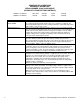
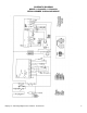
SEQUENCE OF OPERATIONS IMPINGER II ADVANTAGE SERIAL NUMBER 2038616 AND ABOVE (OVENS WITH PUSH BUTTON CONTROLS) MODEL 1154-000-EA MODEL 1155-000-EA POWER SUPPLY CONTROL BOX AUTO COOL DOWN MAIN FAN CIRCUIT BURNER CIRCUIT IGNITION CONTROL TEMPERATURE CONTROL CONVEYOR DRIVE 2 NAT. GAS LP GAS 230VAC 230VAC 50 HZ. 50 HZ. 1 PHASE 1 PHASE Electrical power to be supplied to the oven by a three conductor service. When the temperature in the control box reaches 120°F ± 3°F (48.9°C ± 1.
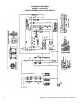
SEQUENCE OF OPERATIONS IMPINGER II ADVANTAGE SERIAL NUMBER 2038616 AND ABOVE (OVENS WITH PUSH BUTTON CONTROLS) MODEL 1164-000-EA POWER SUPPLY MAIN FAN CIRCUIT HEAT CIRCUIT CONVEYOR CONTROL 400/230VAC 50HZ. 3 PHASE Electrical power to be supplied to the oven by a four conductor service. Brown conductor is hot. Black conductor is hot. Black conductor is hot. Green conductor is ground.
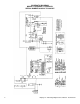
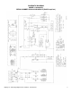
SCHEMATIC DIAGRAM MODEL 1154-000-EA, 1155-000-EA SERIAL NUMBER 2038616 TO 2045407 4 Impinger II – Advantage Digital Service Manual - International
SCHEMATIC DIAGRAM MODEL 1154-000-EA, 1155-000-EA SERIAL NUMBER 2045408 AND ABOVE Impinger II – Advantage Digital Service Manual - International 5
SCHEMATIC DIAGRAM MODEL 1164-000-EA SERIAL NUMBER 2038616 AND ABOVE 6 Impinger II – Advantage Digital Service Manual - International
SCHEMATIC DIAGRAM MODEL 1164-000-EA SERIAL NUMBER 2053336 AND ABOVE (RoHS Compliant) Impinger II – Advantage Digital Service Manual - International 7
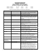
TROUBLESHOOTING GUIDE IMPINGER II ADVANTAGE SERIAL NUMBER 2038616 AND ABOVE (OVENS WITH PUSH BUTTON CONTROLS) MODEL 1154-000-EA MODEL 1155-000-EA NAT. GAS LP GAS 230VAC 230VAC 50 HZ. 50 HZ.
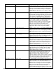
Air pressure switch Oven cavity hi-limit thermostat Ignition control Burner blower motor Air pressure switch (burner blower) Spark generator Igniter/sensor assembly Gas valve Flame will not stay on Flame sensor Impinger II – Advantage Digital Service Manual - International blockage or damage. If above checks are okay, but pressure switch is still not closed, replace gas valve. Check air switch terminals for supply voltage to terminals NO2 and COM.
Power supply Ignition control Oven will not heat Serial Number 2045408 & Above Gas supply Main fan Air pressure switch Oven cavity hi-limit thermostat Ignition control Burner blower motor Air pressure switch (burner blower) Ignition control Igniter/sensor assembly Gas valve 10 Set the temperature to the lowest temperature setting. If there is sufficient microamp current, but the flame will not stay lit, check for proper polarity of the power supply.
Flame will not stay on Flame sensor Power supply Ignition control Low flame is on, but no main flame NOTE: Flame should be on at this time Control transformer Conveyor motor Capacitor, conveyor motor Switch, conveyor reversing Oven control Conveyor motor runs, but there is no speed display shorts. Readings should be as follows, V1 – 2.9K ohms approx., V2 – 1.3K ohms approx. If these readings are not achieved, replace gas valve. If these readings are achieved, replace ignition control.
should be approx. 25-100 Hz. If these readings are not achieved, replace conveyor motor. If the readings are achieved, proceed. If the hall effect sensor readings are correct, but there is no speed indicated on the display, replace the oven control Oven control TROUBLESHOOTING GUIDE IMPINGER II ADVANTAGE SERIAL NUMBER 2038616 AND ABOVE (OVENS WITH PUSH BUTTON CONTROLS) MODEL 1164-000-EA 400/230VAC 50HZ.
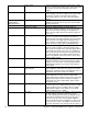
Cooling fan No automatic control box cooling Incoming power supply Oven cavity hi-limit thermostat Fuse, 10 amp Fuse holder Hi-limit thermostat, control box Cooling fan thermostat Cooling fan Oven will not heat Main fan Control transformer Air pressure switch Oven control Thermocouple Impinger II – Advantage Digital Service Manual - International terminals. Replace as needed. Line voltage should now be at the cooling fan. If voltage is present, check motor for opens, shorts or grounds.
Oven control Thermocouple Oven control Mercury contactor Heating element(s) Oven heats with switch off Mercury contactor Intermittent heating Thermal/overload of main fan motor Conveyor will not run Incoming power supply Fuse, 10 amp Fuse holder Hi-limit thermostat, control box Switch, main fan 14 connected to the oven control, and the display indicates “PROBE FAIL”, disconnect the thermocouple from the oven control and measure the resistance of the thermocouple.
Control transformer Conveyor motor Capacitor, conveyor motor Switch, conveyor reversing Oven control Conveyor motor runs, but there is no speed display Check for supply voltage to the primary of control transformer. If no voltage is present, trace wiring back to oven fan switch. If voltage is present, check for 24VAC at transformer secondary. If there is primary voltage, but no secondary voltage, replace control transformer. Check for supply voltage to the conveyor motor at terminal #6 to neutral.
REMOVAL, INSTALLATION AND ADJUSTMENTS IMPINGER II ADVANTAGE SERIES CAUTION BEFORE REMOVING OR INSTALLING ANY COMPONENT IN THE IMPINGER OVEN BE SURE TO DISCONNECT ELECTRICAL POWER AND GAS SUPPLY. MAIN FAN – REPLACEMENT A. Shut off power at main breaker. B. Remove motor cover from back of oven. C. Disconnect wiring and mark for reassembly. D. Remove bolts and slide back straight out of the oven. E. Loosen the bolt from fan hub and remove fan from motor shaft.
FUSE HOLDER – REPLACEMENT A. B. C. D. E. Shut off power at main breaker. Remove control box cover and front panel. Remove wires from fuse holder and mark for reassembly. Remove mounting screws or mounting nut on fuse holder and remove fuse holder. Reassemble in reverse order and check system operation. THERMOSTAT, CONTROL BOX HI-LIMIT – REPLACEMENT A. Shut off power at main breaker. B. Remove control box cover and front panel. C. Remove wires from thermostat and mark for reassembly. D.
TRANSFORMER, CONTROL – REPLACEMENT A. B. C. D. E. Shut off power at main breaker. Remove control panel top and front cover. Remove all wires from transformer and mark for reassembly. Remove two mounting screws from transformer base and remove transformer. Reassemble in reverse order and check system operation. OVEN CONTROL – REPLACEMENT A. B. C. D. E. F. G. Shut off power at main breaker. Remove control box cover and front panel. Remove all wiring connections and mark for reassembly.
A. B. C. D. E. Shut off power at main breaker. Remove control panel top and front cover. Remove wires from control and mark for reassembly. Remove one mounting screw and remove burner control from the gas valve. Reassemble in reverse order and check system operation. GAS VALVE – REPLACEMENT (S/N 2045407 and Below) A. B. C. D. E. F. G. H. I. J. K. Shut off power at main breaker. Shut off gas supply to the oven and disconnect the flexible gas line to oven. Remove control panel top and front cover.
TEMPERATURE REGULATION VALVE – REPLACEMENT A. B. C. D. E. F. G. Shut off power at main breaker. Shut off gas supply to the oven and disconnect the flexible gas line to oven. Remove control panel top and front cover. Remove bypass tube from burner manifold. Remove wiring from valve and mark for reassembly. Remove four mounting nuts from burner manifold and disconnect pipe union. Remove temperature regulation valve and piping from oven. IGNITER/SENSOR ASSEMBLY – REPLACEMENT A. B. C. D. E. F. G. H. I.
A. Shut off power at oven switch. B. Set conveyor reversing switch in the other position. C. Turn oven “on” and check for proper operation. CAPACITOR, CONVEYOR DRIVE MOTOR – REPLACEMENT A. B. C. D. E. Shut off power at main breaker. Remove control panel top and front cover. Discharge capacitor before removing wires. Mark wires for reassembly. Remove mounting screw and remove capacitor. Reassemble in reverse order and check system operation. AIR PRESSURE SWITCH – REPLACEMENT A. B. C. D. E. F.
IMPINGER II ADVANTAGE GENERAL VIEW LETTER A B C D E F G H I J K L M N O P 22 PART NUMBER 369390 369502 370010 369504 3695032 369511 369659 370679 369225 369211 370118 369231 369232 369019 370066 DESCRIPTION Caster 4” w/mounting plate Bottom finger cover Columnating plate, see Installation & Operations manual Bottom finger housing Top finger housing Columnating plate, see Installation & Operations manual Top finger cover Oven top Conveyor hole cover (S/N 2052462 & Below) Conveyor hole cover (S/N 2052463
Impinger II – Advantage Digital Service Manual - International 23
IMPINGER II ADVANTAGE CONTROL BOX 1154-000-EA, 1155-000-EA LETTER A B C D E F G H I J Not Shown K L M N O P Q R S T U V W X Y Z AA BB CC DD EE FF Not Shown GG HH II JJ KK LL MM Not Shown Not Shown 24 PART NUMBER 370108 370355 370107 370354 369432 369378 369579 369574 370362 370384 370676 369575 369025 369689 369901 369566 369524 369654 369939 369590 370397 370186 370031 369557 369589 369401 369580 370400 357067 369192 369771 370359 353082 370178 370176 369376 369698 370383 370682 369507 369431 369014 3571
Impinger II – Advantage Digital Service Manual - International 25
IMPINGER II ADVANTAGE CONTROL BOX 1164-000-EA LETTER A B C D E F G H I J K L M N O P Q R S T U V W X Not Shown Not Shown 26 PART NUMBER 370108 370355 369432 370354 370107 369025 370673 370241 369431 369507 370383 370682 369192 369368 370359 353082 369698 370117 370178 357107 369014 369331 370384 370676 369378 370362 369479 370672 370711 370674 DESCRIPTION Control box top Control, oven On/off switch Facia, Label Side panel Blower Air Switch Blower Air Switch (S/N 2053336 & Above - RoHS Compliant) Transfor
Impinger II – Advantage Digital Service Manual - International 27
OVEN BACK ASSEMBLY LETTER A B C D E F G H I J K L M 28 PART NUMBER 369182 369899 369655 370164 369976 369549 369581 369196 369695 369033 369681 369979 369227 369541 DESCRIPTION Fan Fan shroud Stand off Heating element 230 Volt Rear wall Gas ovens Electric ovens Motor mount Motor Bracket, motor Clamp, motor Cover, back Bracket, hi-limit Spring Bracket, thermocouple Impinger II – Advantage Digital Service Manual - International
Impinger II – Advantage Digital Service Manual - International 29
CONVEYOR / DOOR LETTER A B C D Not Shown PART NUMBER 369611 369664 369269 370116 370671 E 369223 F G H J K L 369224 369666 369226 369516 369514 369515 369978 369238 370678 369513 369510 370016 369501 1123D 369927 369925 369926 369929 369165 369194 369394 M Not Shown N O P Q R S T U W X Y 30 DESCRIPTION Coupler (S/N 2052462 & Below) Coupling center (S/N 2052462 & Below) Ball plunger (S/N 2052462 & Below) Set screw (S/N 2052462 & Below) Drive Coupling (S/N 2052463 & Above) Crumb pan, right, S/N 204545
Impinger II – Advantage Digital Service Manual - International 31
Impinger II – Advantage Digital Service Manual - International