Single Rail Modular KVM Console with 15 / 17 / 19”LCD Panel English User Manual For Installation into a 19” rack it is essential to precisely follow the installation procedure as described in section 3.1. Install the Console into a Cabinet of this manual.
Single Rail Console For Modular KVM Switch User Guide Packing List The complete 15 / 17 / 19” single rail console with modular KVM switch package consists of: • • • • • 1U 19” rack mount console Rails with front and rear bracket x 2 Extended brackets x 2 Short brackets x 2 Bracket attachments x 2 • 15 / 17" LCD Console bracket attachment 19" LCD Console bracket attachment 1.
Single Rail Console For Modular KVM Switch User Guide Safety Instructions 1. Please read these safety instructions carefully. 2. Please keep this User’s Manual for later reference. 3. Please disconnect this equipment from the AC outlet before cleaning. Do not use liquid or sprayed detergent for cleaning. Use a moist sheet or cloth for cleaning. 4. It is recommended that for your convenience the equipment is installed near an easily accessible power socket. 5.
Single Rail Console For Modular KVM Switch User Guide Index of Contents Packing List ......................................................................................................... I Safety Instructions .............................................................................................. II Index of Contents............................................................................................... III 1. General Information ............................................................
Single Rail Console with Modular KVM Switch User’s Manual 1. General Information The LINDY Single Rail consoles offer industrial level input solution to optimize your space utilization by controlling your systems in just 1U. With the unique modular design, you can easily integrate more than 17 models of KVM switches with different functions and expand the connections up to 8 levels of the KVM switches. 1.
Single Rail Console with Modular KVM Switch User’s Manual 1.3 Product Specification 1.3.1 15" Single Rail Console with Modular KVM Switch Specification Model name Number of ports 15” single rail console with modular KVM switch 1 Dimension 470.1 x 447.5 x 44 mm / 18.5 x 17.6 x 1.7 inches Package Dimension 606 x 551.5 x 230 mm / 23.9 x 21.7 x 9.0 inches 12 Kg / 26.5 lbs 19.5 Kg / 43.0 lbs 15 inches Active Matrix TFT LCD Maximum Resolution up to 1024 x 768 (XGA) Supports 0.297 mm x 0.
Single Rail Console with Modular KVM Switch User’s Manual 1.3.2 17" Single Rail Console with Modular KVM Switch Specification Model name Number of ports 17” single rail console with modular KVM switch 1 Dimension 470.1 x 447.5 x 44 mm / 18.5 x 17.6 x 1.7 inches Package Dimension 606 x 551.5 x 230 mm / 23.9 x 21.7 x 9.0 inches 13 Kg / 28.7 lbs 20.5 Kg / 45.2 lbs 17 inches Active Matrix TFT LCD Maximum Resolution up to 1280 x 1024 (SXGA) Supports 0.264 mm x 0.
Single Rail Console with Modular KVM Switch User’s Manual 1.3.3 19" Single Rail Console with Modular KVM Switch Specification Model name Number of ports 19” single rail console with modular KVM switch 1 Dimension 520.1 x 447.5 x 44 mm / 24.5 x 17.6 x 1.7 inches Package Dimension 606 x 551.5 x 230 mm / 23.9 x 21.7 x 9.0 inches Net Weight 14 Kg / 30.9 lbs Gross Weight 21.5 Kg / 47.4 lbs 19 inches Active Matrix TFT LCD Maximum Resolution up to 1280 x 1024 (SXGA) Supports 0.098 mm x 0.
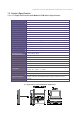
Single Rail Console with Modular KVM Switch User’s Manual 2. Panel Controls and OSD Function Panel Controls Description Soft power on/off button. Adjacent LED is lit when on Auto Auto-synchronize and scale down display to any valid factory preset timings Up Press to scroll the function you want to adjust Down Press to scroll the function you want to adjust Menu To access the main menu. This button also acts as the “Enter” button 2.1 Auto Tune 1. Press Menu 2.
Single Rail Console with Modular KVM Switch User’s Manual 3. Press Menu to enter 4. Use the Up and Down buttons to scroll to the signal input source. 5. Press Menu to enter 2.3 Brightness 1. Press Menu 2. Use the Up and Down buttons to scroll to Brightness 3. Press Menu to enter 4. Use the Up and Down buttons to adjust the Brightness of the display 5. Press Menu to enter 2.4 Contrast 1. Press Menu 2. Use the Up and Down buttons to scroll to Contrast 3. Press Menu to enter 4.
Single Rail Console with Modular KVM Switch User’s Manual 2.6 Position 1. Press Menu 2. Use the Up and Down buttons to scroll to Positioning 3. Press Menu to enter. You will see: Icon Description Image Pos To adjust the position of the image. OSD Pos To adjust the position of the OSD. Return To exit and return to the previous page 4. Use the Up and Down buttons to choose which Position you want to change 5. Press Menu to enter 2.7 Language 1. Press Menu 2.
Single Rail Console with Modular KVM Switch User’s Manual 2.9 Power Indicator GREEN RED RED ON STANDBY SUSPEND RED OFF 3. Installation 3.1 Install 15 / 17 / 19" Single Rail Console into Cabinet 3.1.1 Notes It is essential that each step of this installation guide is completed in the stated order to ensure a successful installation. 1. Please the contents of this box against the list below, before installation. 2. Before installation, make sure all peripherals and computers have been turned off. 3.
Single Rail Console with Modular KVM Switch User’s Manual 3. Short bracket x 2 4. Bracket attachment x 2 15 / 17" LCD console bracket attachment 19" LCD console bracket attachment 5. Flat Screw (length = 6 mm) x 6 6. Screw x 6 7. Key x 2 3.1.3 Step A (Install Console): 1. Adjust the rail until two screws appear.
Single Rail Console with Modular KVM Switch User’s Manual 2. Loosen (but do not remove) all seven screws. 3. Adjust the rail to fit your cabinet 4. Install the front and rear bracket on to the cabinet. 5. Tighten the seven screws from point 2. 6. Repeat points 1~5 for the other side.
Single Rail Console with Modular KVM Switch User’s Manual 7. Push the console part way into the rails. 8. Unlock and pull the rail–lock switch (both sides of the console at the same time) then push console to the end of the rails. lock unlock rail-lock switch 9. Install three flat screws (length = 6 mm) in the rear of the console (each side). 10. Finish the installation as below.
Single Rail Console with Modular KVM Switch User’s Manual 3.1.4 Step B (Replace short bracket): 1. Remove all seven screws. 2. Take the two original brackets out. original bracket original bracket 3. Insert the short bracket in to the rear of the rail. short bracket 4. Insert four screws (don’t tighten) to combine the rail, short bracket and bracket attachment. bracket attachment short bracket 5. Repeat points 1~4 for the other side. 6. Repeat points 3~10 of Step A to finish the installation.
Single Rail Console with Modular KVM Switch User’s Manual 3.1.5 Step C (Replace extended bracket): 1. Loosen (but do not remove) all seven screws. 2. Remove six screws, as shown below. 3. Take the rear bracket out. rear bracket 4. Adjust the rail and input the extended bracket to the rear of the rail. Now adjust the extended bracket to fit your cabinet. Insert 2 or 3 screws (but don’t tight-up) at the length you need. Do not install using one screw. extended bracket 5.
Single Rail Console with Modular KVM Switch User’s Manual 3.1.6 Unloading Step 1. Ensure that the console is locked and turned off. 2. Loosen the two thumb screws and pull out the modular KVM switch. 3. Release three screws in rear of the console. (Both sides) 4. Unlock. 5. Pull the console out until it reaches the console lock.
Single Rail Console with Modular KVM Switch User’s Manual 6. Pull the rail-release switch (both sides) and pull the console out. Be careful when pulling out the console. rail-release switch 7. Push the rail-lock switch on the rail and push the rail back.
Single Rail Console with Modular KVM Switch User’s Manual 3.2 Install Modular KVM Switch Step 3.2.1 Hardware Kits Contents 1. Bracket with thumb screw x 2 2. Screw (length = 6 mm) x 4 3.2.2 Install Modular KVM Switch Step 1. Install two screws (length 6mm) to attach the Bracket to the KVM Switch at each side 2. From the rear of the cabinet slide the KVM Switch along the rails, until it reaches the console and the thumb screws are aligned to the rear of the cabinet.
Single Rail Console with Modular KVM Switch User’s Manual 3.Tighten the Thumb Screws of Bracket A, at each side, to fix the position of the KVM Switch and complete the installation 3.3 Installing the Video Card and Video Driver Before connecting the LCD console, make sure your computer has a video card already installed for the monitor. After you connect the console, install the video driver.
Single Rail Console with Modular KVM Switch User’s Manual Whenever you change the resolution, color, or refresh rate, the image size, position, or shape may change. This behavior is normal. You can readjust the image using the monitor on-screen controls. For more information on the monitor on-screen controls, refer to Chapter 2. For more information on configuring the display settings, refer to the manual that came with your video card. 3.
Single Rail Console with Modular KVM Switch User’s Manual 3.7 Testing the Console To test that the console is working properly, perform the following steps: 1. Power up the console, and then turn on your computer. 2. If the unit does not power up when the panel is pulled up, try pushing the soft power on/off button on the left or under side of the monitor panel to power up the unit. 3. Make sure the video image is centered within the screen area.
WEEE, Recycling of Electronic Products (Europe) WEEE (Waste of Electrical and Electronic Equipment), Recycling of Electronic Products In 2006 the European Union introduced regulations (WEEE) for the collection and recycling of all waste electrical and electronic equipment. It is no longer allowable to simply throw away electrical and electronic equipment. Instead, these products must enter the recycling process.
Radio Frequency Energy, Certifications Shielded cables must be used with this equipment to maintain compliance with radio frequency energy emission regulations and ensure a suitably high level of immunity to electromagnetic disturbances. FCC Warning This equipment has been tested and found to comply with the limits for a Class B digital device, pursuant to part 15 of the FCC Rules. These limits are designed to provide reasonable protection against harmful interference in a residential installation.