CPU Switch P/PXT Series User Manual Benutzerhandbuch Manuel Utilisateur Manuale d’uso 4 Port Model: 8 Port Model: 16 Port Model: CPU Switch P-Series LINDY No. 32503 LINDY No. 32504 LINDY No. 32505 English Deutsch Français Italiano CPU Switch PXT-Series LINDY No. 32512 LINDY No. 32513 LINDY No. 32514 www.LINDY.
User Manual................Page 1 Benutzerhandbuch.....Page 18 Manuel Utilisateur.......Page 34 Manuale d’uso.............
English Manual Introduction Thank you for purchasing this LINDY P/PXT-Series CPU Switch. Please read this manual carefully to understand the functions and features of your new Switch. About this manual - This manual covers the P-Series and Dual Console PXT-Series CPU Switches. These switches share many of the same functions. Where there is a difference this is clearly stated. Using LINDY P/PXT-Series CPU Switches you can save on the additional cost of multiple keyboards, monitors and mice.
English Manual Product Features 4/8/16 port KVM switch in a 1U, 19” rackmount size design Single console operation (P-Series) Dual console operation with integrated CAT5 KVM Extender (PXT-Series only) Includes CAT5 Remote Console Receiver Switch (PXT-Series only) Support for LINDY mice and for all mice up to 5 buttons and 2 wheels with fully Microsoft compatible drivers.
English Manual Package contents P-Series Switches LINDY CPU Switch P4, P8 or P16 model Power Adapter 19” Rackmount Kit This manual PXT-Series Switches LINDY CPU Switch P4XT, P8XT or P16XT model CAT5 Extender Remote Console Receiver module 1x 3-in-1 KVM cable to connect the workstation to the Remote Console Receiver Two Power Adapters (1 x CPU Switch, 1 x Remote Console Receiver) 19” Rackmount Kit This manual Optional Cables and Accessories (not included) Combined (3-in-1) KVM Cab
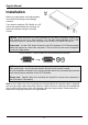
English Manual Installation Before you start please verify that all parts are included according to the package contents. If you want to install the CPU Switch in a 19” server rack please attach the enclosed 19” rackmount brackets using the included screws. P-Series - Apart from the PCs to be connected you will need a keyboard, monitor and PS/2 mouse to use as a local console. You will also need standard 3-in-1 KVM connection cables to connect the computers to the LINDY CPU Switch P4 and P8.
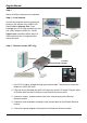
English Manual Step 1 Switch off all the computers to be attached. Step 2 – Local Console Connect the keyboard, monitor and mouse directly to the sockets of the LINDY CPU Switch labelled Console Port. If your keyboard has a 5 Pin DIN connector you can use a PS/2 adaptor (LINDY No. 70129). Please note: Serial Mice with 9 Way D or USB connectors are not supported and cannot be used! Step 3 – Remote Console (PXT only) To Power Adapter 1. Use CAT5 or higher, straight through type network cable.
English Manual 6. When using CAT5/5e/6 cable over a distance greater than 90m (300 feet), please set the DIP switches at the rear of the CPU Switch to ON/ON. (Please note that video resolutions over 1280x1024 are not supported for distances greater than 90m) Note: Both local and remote consoles have the same priority control of the switch and the connected computers.
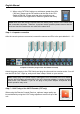
English Manual Cascading / Daisy Chaining of multiple CPU Switches You can integrate up to 8 CPU Switches in one KVM daisy chained installation. Using the CPU Switch P16 or P16XT, this gives a maximum of 128 attached computers. Please note: If the daisy chain cable length over all CPU Switches exceeds 10m (30 feet) and picture quality deteriorates, a VGA amplifier such as the LINDY VGA Extender (LINDY No. 32386) can be used.
English Manual Step 4 – Resetting the Switches After you have connected and switched on the SLAVE CPU switches and computers, all of the CPU switches must be reset. First, reset the SLAVE CPU Switch at the end of the daisy chain and then reset all of the other SLAVE switches up to the MASTER CPU switch. To reset the switch, press and hold the Bank button and P4 or P8 button (depending on model) on the front panel of the switch. Each SLAVE switch should now show a dash in its BANK display.
English Manual Operation Important note: Your monitor will only display one PC signal at any one time. All keyboard and mouse commands are sent to this PC only. After initial power up, port 1 is active by default. When a PC is connected to the currently selected port and it is not switched on, or is in sleep mode, the monitor will not display any signal. Password Security When you power on the CPU Switch it will ask you for a password. The default password is eight zeros –“00000000”.
English Manual PXT-Series Remote Console Operation: When using the CAT5 Remote Extender unit you can switch between computers using hotkey and OSD. To access the CPU Switch you must switch to KVM console operation. Scroll Lock + Scroll Lock + C = Switches between local workstation access and CPU Switch remote console operation Port LED Display The front panel of the CPU Switch has two LEDs for each port. When the LED labelled “P” is illuminated GREEN a computer attached to this port is powered on.
English Manual Keyboard Hotkey Selection You can also conveniently select the computer to be accessed and displayed by switching ports through simple keyboard key sequences. To send commands to the KVM switch, the “SCROLL LOCK” key must be pressed twice within 2 seconds. You will hear a beep to confirm that the keyboard is in hotkey mode. If you have not pressed any key in hotkey mode within 2 seconds, the keyboard will return back to Operating System control status.
English Manual Auto Scan mode: Scroll Lock + Scroll Lock + S = Auto Scan (Press any key to exit Auto Scan Mode) Beeper Function (Enables and Disables beep during Auto Scan): + Scroll Lock + Scroll Lock + B = Beeper PXT-Series Remote Console Operation: When using the CAT5 Remote Extender unit you can switch between servers by hotkey and OSD. To access the CPU Switch you must switch to KVM console operation.
English Manual On Screen Display Menu (OSD) port selection The On Screen Display menu provides a lot of information about the CPU Switch and the attached computers, and offers advanced administration features and full CPU Switch control to the user.
English Manual The OSD Menu displays the following screen for a 16 port CPU Switch. For a 4 port or 8 port model you will find less ports listed respectively. a. You can toggle between the 3 parts of the OSD menu (Bank PC names, CPU Switch Settings) using the TAB key. The lower light blue part of the OSD lists keyboard controls.
English Manual i. OSD means that the OSD window is displayed on your monitor for 10 sec. You can modify this value from 05 sec to 99 sec. Default is 10 sec. j. SCAN displays the scan duration per channel in Auto Scan Mode. The default SCAN time is 10 sec., the maximum scan time can be set to 99 sec, it cannot be less then 5 sec. k. CONSOLE ON/OFF is used to prevent unauthorized use of the console. “CONSOLE ON” means that any user can access the console.
English Manual Troubleshooting If none of the LED displays of the CPU Switch are illuminated please check that the power adapter is connected and switched on at the mains. The polarity is centre positive and the power adapter needs to be DC 12V, 1A (or minimum DC 9V, 1A). PXT models only: From the Remote CAT5 console the OSD is only available when you have switched access from the local workstation to the CPU Switch. For troubleshooting the CAT5 Remote Console unit, please see the end of this section.
English Manual d. Avoid moving the mouse or pressing the mouse buttons when switching ports. e. Avoid switching ports during the PC shut down process. 7. If you have forgotten the “password” please contact LINDY. PXT models only: If everything works fine using the local console access to the CPU Switch, but problems occur when you try to access from the CAT5 Extender please check the following.
Deutsches Handbuch Überblick Herzlichen Dank dass Sie sich für einen KVM-Switch aus der LINDY P/P-XT-Serie entschieden haben . Bitte lesen Sie dieses Handbuch sorgfältig um alle Möglichkeiten zu erfassen, die Ihnen dieser KVM-Switch bietet. Über dies Handbuch – Dies Handbuch beschreibt die LINDY CPU Switch P-Serie und die Dual Console P-XT-Serie. Diese KVM-Switches stimmen in den meisten Funktionen überein. Wo sie sich unterscheiden wird klar darauf hingewiesen.
Deutsches Handbuch Eigenschaften 4/8/16 Port KVM-Switch im kompakten 19” Rackmount-Gehäuse mit nur einer Höheneinheit Zentraler Zugriff von einen Arbeitsplatz - Single console operation (P-Serie) Zentraler Zugriff von zwei Arbeitsplätzen - Dual console operation – mit integriertem KVM Cat.5 Extender (nur P-XT-Serie) Inklusive KVM Cat.
Deutsches Handbuch Lieferumfang CPU Switches der P-Serie LINDY CPU Switch P4, P8 oder P16 Netzteil 19” Einbaukit (Winkel und Schrauben) Dies Handbuch PXT-Series Switches LINDY CPU Switch P4XT, P8XT or P16XT Cat.5 KVM Extender Remote Console Switch 1x 3-in-1 KVM-Kabel zum Anschluss des Bürorechners an den Cat.5 KVM Extender Remote Console Switch Zwei Netzteile (1 x CPU Switch, 1 x Cat.
Deutsches Handbuch Installation Bevor Sie mit dem Aufbau beginnen, prüfen Sie bitte ob alle Teile enthalten sind. Siehe hierzu die vorstehende Liste Lieferumfang. Falls Sie den LINDY CPU Switch in einem 19“ Rack einbauen wollen befestigen Sie bitte die 19“ Montagewinkel mit den beiliegenden Schrauben. P-Serie - Neben den anzuschließenden Rechnern benötigen Sie lediglich einmal Monitor, Maus und Tastatur sowie die notwendigen Anschlusskabel mit Standardanschlüssen.
Deutsches Handbuch Schritt 1 Schalten Sie alle Geräte aus. Schritt 2 – Lokale Konsole (am CPU Switch) Verbinden Sie Tastatur, Maus und Monitor mit dem CPU Switch an den Ports mit der Bezeichnung Console port. Falls Ihre Tastatur einen 5poligen DIN Stecker hat benötigen Sie eine neuere Tastatur oder einen PS/2-Adapter, z.B. LINDY Art. Nr. 70129. Der Anschluss von USB-Mäusen oder von seriellen Mäusen mit 9polgem D-Anschluss wird NICHT unterstützt ! Schritt 3 – Cat.
Deutsches Handbuch 6. Bei Verwendung von Netzwerkkabel mit einer Länge über 90m setzen Sie bitte beide DIP-Schalter am CPU Switch auf ON/ON. Beachten Sie bitte, dass Auflösungen über 1280x1024 für Distanzen über 90m nicht unterstützt werden HINWEIS: Beide Konsolen, Local und Remote, haben die gleiche Priorität beim Zugriff auf den KVM Switch und damit auf die angeschlossenen Server. Sie zeigen immer den gleichen Server.
Deutsches Handbuch Daisy Chain Kaskadierung mehrerer CPU Switches Bis zu 8 CPU Switches können in einer KVM Daisy Chain Installation integriert werden. Bei Verwendung von CPU Switch P16 oder P16XT ergibt dies maximal 128 Server. Bitte beachten Sie, dass bei Überschreitung einer Daisy-Chain-Buslänge über alle Switches von 8m eventuell ein VGA-Extender ( LINDY Art.Nr. 32386) eingesetzt werden muss.
Deutsches Handbuch Schritt 4 – Resetten der Switches Nach Anschluss, Einschalten und Booten aller Switches und Rechner müssen alle CPU Switches RESETTET werden, und zwar zuerst der entfernteste SLAVE CPU Switch und zum Schluss der MASTER CPU Switch. Die Slaves sollten jeweils nach dem eigenen Reset einen Strich im Bank Display anzeigen. Zuletzt wird der Master resettet. Danach zeigt der Master eine 1 und die Slaves in Ihrer Reihenfolge die entsprechende Ziffer an.
Deutsches Handbuch Betrieb Wichtiger Hinweis: Ihr Monitor zeigt immer nur ein Videosignal, das des gerade gewählten Ports. Alle Tastatur- und Mauskommandos werden nur an den Rechner gesendet, der gerade ausgewählt ist. Falls ein PC nicht eingeschaltet ist oder sich in einem Energiesparmodus (Sleep Mode) befindet, wird der Monitor kein Signal anzeigen! Bitte beachten Sie, dass dies NICHT ein Zeichen für einen Defekt am CPU Switch ist.
Deutsches Handbuch P-XT-Modelle: Bedienung via Cat.5 Extenderbox: Von der an die Cat.5 Extenderbox angeschlossenen Konsole schalten Sie zwischen Zugriff auf den lokalen Arbeitsplatzrechner und Zugriff auf den CPU Switch und damit das OSD mit untenstehendem Hotkey um.
Deutsches Handbuch Direkte Port-Anwahl / Tastatur HotKey Kommandos: Sie können bequem von der Tastatur aus die Ports bzw. Rechner anwählen. Dazu drücken Sie zweimal kurz hintereinander die ROLLEN-Taste. Zur Bestätigung sendet der CPU Switch einen Signalton und versetzt die Tastatur kurzzeitig (ca. 2 Sekunden) in den Kommandomodus. Weitere Tasteneingaben müssen daher immer kurzfristig erfolgen.
Deutsches Handbuch Portauswahl über das On-Screen-Display Menue ( OSD ) P-XT-Modelle: Bedienung via Cat.5 Extenderbox: Von der an die Cat.5 Extenderbox angeschlossenen Konsole schalten Sie zwischen Zugriff auf den lokalen Arbeitsplatzrechner und Zugriff auf den CPU Switch und damit das OSD mit folgendem Hotkey um. Rollen + Rollen C + = Schaltet Zugriff zwischen lokalem Arbeitsplatzrechner und Zugriff auf den CPU Switch und damit das OSD um P-XT Modelle: von der an die Cat.
Deutsches Handbuch Das OSD Menü klappt in der unten abgebildeten Form auf dem Monitor auf. Bei Verwendung eines 4 oder 8 Port CPU Switch P4 oder P8 finden sich entsprechend weniger Servereinträge im OSD. Zwischen 3 unterschiedlichen Breichen des OSD (1. Bank, 2. Rechnernamen, 3. SwitchEinstellungen) kann durch Drücken der Tabulator-Taste hin und her gewechselt werden. a.
Deutsches Handbuch f. Der dritte Teil des OSD mit den Konfigurationseinstellungen wird durch Drücken der SCAN: 1 0 SEC. CONSOLE ON/OFF Tabulatortaste selektiert. Das Handsymbol zeigt das aktuell gewählte Feld, Drücken der TAB-Taste wechselt zwischen den Feldern, neue Werte überschreiben alte bei Eingabe. g. “ OSD: 10 SEC ” zeigt die Zeit, nach der sich das OSD automatisch wieder ausblendet sobald keine Taste mehr gedrückt wird. Default ist 10 Sek., Werte von 5 bis 99 Sekunden können eingegeben werden. h.
Deutsches Handbuch Hilfe bei Problemen Falls keine der LED Anzeigen an der Frontseite des CPU Switch leuchtet kann das Gerät komplett defekt sein. Bitte prüfen Sie das Netzteil (und ob ggf. der Netzschalter an der Geräterückseite) eingeschaltet ist. Das Netzteil sollte 9-12V DC 1A liefern mit positiver Spannung auf dem zentralen Anschluss. P-XT Modelle: von der an die Cat.
Deutsches Handbuch b. Stellen Sie sicher, dass die Maus eine PS/2 Maus ist. Versuchen Sie es mit einer anderen PS/2 Standard-Maus. Verschiedene Mäuse, wie manche Funkmäuse, 5-und mehr-Tasten-Mäuse verwenden sehr ungewöhnliche und proprietäre PS/2-Bussignale. LINDY CPU Switch P4/P8/P16 sowie die P-XT-Modelle haben eine erweiterte Kompatibilität mit solchen Nicht-Standard-Mäusen, können aber natürlich nicht alle am Markt befindlichen Mäuse und ihre oft proprietären Protokolle unterstützen.
Manuel en Français Introduction Merci d’avoir acheté ce commutateur KVM P/PXT LINDY. Veuillez lire ce manuel avec attention pour comprendre les fonctionnalités et les caractéristiques de ce nouveau commutateur. A propos de ce manuel – Ce manuel couvre la série de commutateurs KVM P et PXT. Ces commutateurs partagent plusieurs fonctions identiques. Il vous sera indiqué lorsqu’il y aura des différences entre les deux produits.
Manuel en Français Caractéristiques du produit Commutateur KVM 4/8/16 ports, 1U, au design rackable 19” Connexion de console simple (Série P) Mode double console avec extension CAT5 intégrée (Série PXT uniquement) Récepteur Extender CAT5 inclus (Série PXT uniquement) Support des souris LINDY et toutes les souris jusqu’à 5 boutons et 2 molettes avec des pilotes compatibles Microsoft.
Manuel en Français Contenu de l’emballage Commutateurs de la Série P LINDY KVM Switch P4, P8 ou P16 Adaptateur d’alimentation Kit de montage en rack 19” Ce manuel Commutateurs Série PXT LINDY KVM Switch P4XT, P8XT ou P16XT Module Extender CAT.
Manuel en Français Installation Avant de commencer, vérifiez que tous les éléments sont inclus dans le packaging. Si vous souhaitez installer le commutateur KVM dans un rack 19”, veuillez utiliser le kit de montage en rack 19” inclus. Série P – A part les connexions au PC, vous devez connecter un écran, clavier et souris PS/2 en tant que console locale. Vous aurez également besoin de câbles de connexions standards KVM 3-en-1 pour connecter les PCs au LINDY KVM P4 et P8.
Manuel en Français Etape 1 Eteignez tous les ordinateurs connectés. Etape 2 – Console locale Connectez le clavier, écran et souris directement aux connexions du LINDY KVM Switch nommés Console Port. Si votre clavier possède une connexion DIN-5, vous pouvez utiliser un adaptateur PS/2 (LINDY No. 70129). Remarque: Les souris série avec un connecteur Sub-D 9 ou avec des connecteurs USB ne sont pas supportés! Etape 3 – Console distante (PXT seulement) Vers Alim. 1.
Manuel en Français 6. Lors de l’utilisation de câble réseau CAT5/5e/6 sur une distance supérieure à 90m (300 pieds), veuillez régler le DIP switch à l’arrière du KVM sur ON/ON. (Remarquez que des résolutions vidéo supérieures à 1280x1024 ne sont pas supportées sur des distances supérieures à 90m) Remarque: Les consoles locales et distantes ont le même niveau de priorité de contrôle sur le commutateur et les ordinateurs connectés.
Manuel en Français Cascade de plusieurs commutateurs KVM Vous pouvez intégrer jusqu’à 8 commutateurs KVM dans une installation cascadée. En utilisant le commutateur KVM P16 ou P16XT, cela vous donne la possibilité de connecter 128 PCs max. Remarque: Si la longueur de cascade totale de tous les commutateurs KVM excède 10m (30 pieds) et la qualité de l’image se dégrade, un amplificateur VGA comme le LINDY VGA Extender (LINDY No. 32386) peut être utilisé.
Manuel en Français Etape 4 – Réinitialisation des commutateurs Après que vous ayez connecté et allumé les commutateurs ESCLAVE et les ordinateurs, tous les commutateurs KVM doivent être réinitialisés. Réinitialisez le commutateur ESCLAVE en premier à la fin de la chaîne de cascade, puis faites de même pour tous les autres ESCLAVE pour terminer par le commutateur KVM MAITRE.
Manuel en Français Utilisation Sécurité par mot de passe Lorsque vous allumez le commutateur KVM, il vous demandera un mot de passe. Le mot de passe par défaut est 8 zéros –“00000000”. Entrez donc les huit zéros dans le champ du mot de passe. Remarque: Ne modifiez pas le mot de passe tant que vous ne vous êtes pas familiarisé avec le fonctionnement du menu OSD – gardez le mot de passe par défaut “00000000”.
Manuel en Français Fonctionnement du module PXT distant: Lors de l’utilisation du module Extender CAT5, vous pouvez commuter entre les ordinateurs en vous servant des raccourcis clavier ou du menu OSD. Pour accéder au commutateur KVM vous devez utiliser la console locale. Arrêt Défil + Arrêt Défil + C = Commutation entre la station de travail et le commutateur Affichage par LED des ports Le panneau frontal du commutateur KVM possède deux LEDs pour chaque port.
Manuel en Français Sélection par raccourci clavier Vous pouvez également sélectionner les ordinateurs par une simple séquence de raccourci clavier. Pour envoyer les commandes au commutateur KVM, la touche “ARRET DEFIL” doit être pressée deux fois en moins de 2 secondes. Vous allez entendre un bip pour vous confirmer que le clavier est bien en mode raccourci clavier. Si vous n’avez pas pressé les touches en moins de deux secondes, le clavier va retourner en mode normal.
Manuel en Français Mode Auto Scan: Arrêt Défil + Arrêt Défil + S = Auto Scan Fonction Bip (Active et désactive le bip pendant le mode Auto Scan): + Arrêt Défil + Arrêt Défil + B = Bip Utilisation de la console distante PXT: Lors de l’utilisation du boîtier Extender CAT5 vous pouvez commuter soit avec les raccourcis clavier, soit avec le menu OSD.
Manuel en Français Sélection des ports par le menu OSD Le menu OSD (On Screen Display) vous fournit une quantité d’informations concernant le commutateur KVM et les ordinateurs connectés, et vous offre des possibilités d’administration avancées et un contrôle total de l’utilisateur du KVM Switch.
Manuel en Français Le menu OSD affiche l’écran suivant pour le modèle 16 ports. Pour le modèle 4 ports ou 8 ports vous retrouverez moins de noms d’ordinateurs. a. Vous pouvez basculer entre 3 parties du menu OSD (Rangée de noms PC, Réglages du KVM) en utilisant la touche TAB. La partie inférieure du menu OSD affiche les contrôles clavier disponibles. b.
Manuel en Français i. OSD signifie que la fenêtre OSD est affichée sur votre moniteur pour 10 sec. Vous pouvez modifier ces valeurs de 05 sec à 99 sec. Le réglage par défaut est de 10 sec. j. SCAN affiche la durée du scan entre les ports en mode Auto Scan. Le temps de scan par défaut est de 10 sec., le temps de scan maximum peut être réglé de 5 à 99 sec, il ne peut pas être inférieur à 5 sec. k. CONSOLE ON/OFF est utilisé pour prévenir d’un accès non autorisé à la console.
Manuel en Français Problèmes Rencontrés Si aucun des affichages par LED sur le commutateur KVM n’est allumé, vérifiez bien que l’adaptateur d’alimentation soit branché au secteur. La polarité est positive au centre et l’adaptateur d’alimentation est en DC 12V, 1A (ou minimum DC 9V, 1A). Modèle PXT uniquement: À partir module distant CAT5, l’affichage par menu OSD est seulement disponible si vous avez commuté l’ordinateur local à partir du commutateur KVM.
Manuel en Français d) e) Evitez de déplacer le curseur de la souris lors de la commutation entre les ports. Evitez de commuter les ordinateurs lorsque ces derniers sont en train d’être éteints.
Manuale Italiano Introduzione Grazie per aver acquistato un LINDY CPU Switch Serie P/PXT. Leggere attentamente questo manuale per sfruttare al meglio le funzioni e le caratteristiche del Vostro nuovo Switch. Manuale – Questo manuale descrive il funzionamento dei CPU Switch Serie P e PXT Dual Console. Questi switch hanno in comune molte funzioni. Le caratteristiche che li distinguono saranno evidenziate.
Manuale Italiano Caratteristiche KVM Switch con 4/8/16 porte, possibilità di montaggio a rack 19”, 1U Console singola (Serie P) Doppia console con porta per CAT5 KVM Extender integrata (solo Serie PXT) CAT5 Remote Console Receiver Switch incluso (solo Serie PXT) Supporta tutti i mouse LINDY ed altri mouse con un Massimo di 5 tasti e due rotelline, installati con driver Microsoft.
Manuale Italiano Contenuto confezione Switch Serie P LINDY CPU Switch P4, P8 o P16 Alimentatore Kit per montaggio a rack 19” Manuale Switch Serie PXT LINDY CPU Switch P4XT, P8XT o P16XT Unità CAT5 Extender Remote Console Receiver 1 cavo 3-in-1 KVM per collegare la workstation al Remote Console Receiver Due alimentatori (1 x CPU Switch, 1 x Remote Console Receiver) Kit per montaggio a rack 19” Manuale Cavi ed accessori opzionali (non inclusi) Cavo KVM Combi (3-in-1) (per P4/P8, PX
Manuale Italiano Installazione Prima di iniziare verificare che tutto il materiale sopra elencato sia incluso nella confezione. Se dovete installare il CPU Switch in un server rack 19”, installate il kit di alette incluso nella confezione. Serie P – Oltre ai PC è necessario avere un set composto da una tastiera, un mouse e un video da utilizzare come console. Vi serviranno anche dei cavi COMBO standard 3in-1 KVM per connettere i computer ai CPU Switch LINDY P4 e P8.
Manuale Italiano Passo 1 Spegnete tutti i computer da collegare Passo 2 – Console Locale Collegate tastiera, monitor e mouse direttamente alle porte del LINDY CPU Switch indicate dalla dicitura Console Port. Se le vostre tastiere hanno un connettore a 5 pin DIN utilizzate un adattatore PS/2 (come il LINDY No. 70129). Nota bene: Mouse Seriali con connettori 9 pin Sub-D o USB non sono supportati e non possono essere utilizzati! Passo 3 – Console Remota (Solo Modelli PXT) All’alimentatore 1.
Manuale Italiano 6. Quando utilizzate un cavo CAT5/5e/6 più lungo di 90m per favore posizionate i due DIP switches posti sul retro del CPU Switch su ON/ON. (Notate che risoluzioni video superiori a 1280x1024 non sono supportate con cavi più lunghi di 90m) Nota: Entrambe le console remota e locale hanno la stessa priorità di intervento nelle operazioni con i PC e il CPU Switch. Per questo motivo assicuratevi che le due console non vengano utilizzate contemporaneamente in modo da evitare errori imprevisti.
Manuale Italiano Installazione e utilizzo di più CPU Switch in cascata E’ possibile integrare fino a 8 CPU Switch in una singola installazione in cascata. Utilizzando i CPU Switch P16 o P16XT, è possibile arrivare ad un massimo di 128 PC controllati. Nota Bene: Se la lunghezza dei cavi di connessione supera i 10m è possibile che la qualità del segnale VGA si deteriori. E’ possibile utilizzare un amplificatore VGA come il LINDY VGA Extender (Part No. 32386) per compensare il problema.
Manuale Italiano Passo 4 – Eseguire il reset degli Switch Dopo aver connesso e acceso i CPU Switch SLAVE e i computer, tutti i CPU switch devono essere reinizializzati. Per primo, eseguite il reset del CPU Switch SLAVE alla fine della catena e poi risalite reinizzializzando tutte le altre unità SLAVE fino ad arrivare all’unità MASTER. Per eseguire il reset tenete premuto il tasto Bank o il tasto di Switch (per i modelli P4 o P8) sul pannello frontale dello Switch.
Manuale Italiano Utilizzo Funzione Password Quando accendete il CPU Switch vi verrà richiesta una password. La password di default è formata da 8 zeri –“00000000”. Inserite gli 8 zeri nel campo. Nota: Non modificate la password fino a che non avrete dimestichezza con il menù OSD e le relative operazioni – per esempio mantenete la password di default “00000000”. Nel caso in cui dimentichiate la password sarà necessario inviare l’unità all’assistenza tecnica Lindy per cancellarla.
Manuale Italiano Selezione della Porta/Computer Potete selezionare la porta da utilizzare in tre modi differenti: Premendo il tasto sul pannello frontale dello Switch Utilizzo combinazioni di tasto HotKey dalla tastiera Menù di selezione On Screen Display Serie PXT- Operazioni dalla Console Remota: Utilizzando il Remote Extender CAT5 potrete passare da un PC all’altro con I tasti Hotkey e il menu OSD.
Manuale Italiano Selezione tramite tasti Hotkey E’ possibile selezionare velocemente il PC da utilizzare tramite una semplice sequenza di tasti da premere sulla tastiera. Per inviare comandi al KVM Switch premere il tasto “Bloc Scorr” per due volte in un tempo massimo di 2 secondi. Sentirete un segnale acustico di conferma dell’ingresso in modalità comandi.
Manuale Italiano Modalità Auto Scan: Bloc Scorr + Bloc Scorr + S = Auto Scan (Premete un tasto qualsiasi per uscire) Funzione Beeper (Abilita e Disabilita il segnale acustico durante l’Auto Scan): + Bloc Scorr + Bloc Scorr + B = Beeper On/Off Serie PXT: Operazioni da Console Remota: Utilizzando l’Unità Extender CAT5 è possibile selezionare il server da controllare tramite Hotkey e menù OSD.
Manuale Italiano Selezione delle porte con menù On Screen Display (OSD) Il menù On Screen Display fornisce all’utente molte informazioni sul CPU Switch e i computer connessi oltre ad offrire funzioni avanzate di amministrazione e pieno controllo del CPU Switch.
Manuale Italiano Il menù OSD Menu per i modelli a 16 porte appare come il seguente. Per i modelli 4 porte o 8 porte troverete solo meno porte elencate. a. Potete spostarvi fra le tre sezioni principali (Bank , PC names, CPU Switch Settings) utilizzando il tasto TAB. La sezione inferiore in blu chiaro della finestra elenca i comandi attivi richiamabili da tastiera.
Manuale Italiano h. Per accedere alla terza sezione del enu OSD contenente le OSD : 10 SEC. ( CHANGE PASSWORD funzioni OSD, SCAN, CHANGE PASSWORD, CONSOLE ON/OFF, SCAN: 10 SEC. CONSOLE ON/OFF etc. utilizzate il tasto “TAB”. Il tasto TAB passa in tutti campi visualizzati. Sovrascrivete I valori presenti con quelli che preferite. i. OSD indica il tempo in cui la finestra OSD rimane visualizzata prima di chiudersi automaticamente. Potete scegliere un numero fra 5 e 99 secondi. Il valore di Default è 10 sec. j.
Manuale Italiano Quando avete selezionato una determinata porta dello switch i comandi di mouse e tastiera vengono inviati direttamente al PC prescelto e il segnale video proveniente dal PC è visualizzato sul monitor. Subito dopo la commutazione verrà visualizzata una piccola 102 ☼SYSTEM 02 finestra con le informazioni essenziali sulla porta selezionata (numero porta, nome e stato del computer connesso) Potete in ogni momento chiudere qualsiasi finestra in sovrimpressione utilizzando il tasto ESCAPE.
Manuale Italiano Risoluzione dei Problemi Se nessuno dei LED sul pannello frontale dello switch è illuminato controllare che l’alimentatore sia correttamente connesso allo switch e sia alimentato. La polarità del connettore è positiva al centro e i parametri di alimentazione ottimali sono DC 12V, 1A (i minimi sono minimo DC 9V, 1A). Solo per modelli PXT: Dalla console Remota CAT5 il menù OSD è disponibile solo dopo essere passati dal controllo della Workstation Locale a quello del CPU Switch.
Manuale Italiano b) c) d) e) 7. Controllate che il mouse sia PS/2 nativo. Molti combo mouse funzionano solo se connessi in modalità PS/2 con il proprio adattatore specifico. Provate ad utilizzare un altro mouse. Alcuni mouse con funzionalità avanzate come radio-mouse, mouse a 5 pulsanti e particolari mouse con rotella utilizzano segnali proprietari non riconosciuti e riproducibili dal KVM Switch.
Technical Data and Radio Frequency Energy Model CPU Switch P4 No. 32503 Console (User) / Server Ports 1 / 4 CPU Switch P8 No. 32504 1/8 Console / User Ports VGA (HD-15 female) + 2x PS/2 (MD-6 female) PC / Server Ports External Power Supply VGA (HD-15 female) + VGA (HD-15 female) + 2x PS/2 (MD-6 female) 2x PS/2 (MD-6 female) 9-12VDC 1A, approx. 1.8m cable Operating Temperature +5°C ... 40°C, for indoor use only Humidity 5 bis 85% rel.H.