LINDY CPU Switch Multiscreen Range Installation and Use Part 32346 Model LINDY CPU Switch Multiscreen 2 ports, 2 screens Part 32347 Model LINDY CPU Switch Multiscreen 4 ports, 2 screens Part 32348 Model LINDY CPU Switch Multiscreen 2 ports, 4 screens Part 32349 Model LINDY CPU Switch Multiscreen 4 ports, 4 screens CPU Switch Multiscreen - Installation and Use First Edition (August 2001) Part Numbers 32346, 32347, 32348 and 32349 © 2001 LINDY Electronics Ltd.
GB USA A PDF version of this manual may be downloaded from: www.lindy.com Quick Installation and Operation Guide QUICK INSTALLATION Power off all your computers and connect them to the computer ports (labelled 1 to 4) on the rear of the LINDY CPU Switch Multiscreen. LINDY 3-in-1 keyboard/video/mouse combination cables are recommended for the keyboard, mouse and first video connection. LINDY video cables are recommended for the additional video connections.
D Komplette Handbuchversion ist herunterladbar von: www.lindy.com Kurzhandbuch, Einführung FEATURES Der LINDY CPU Switch Multiscreen unterstützt Monitorauflösungen bis 1900x1440 bis 75Hz sowie DDC Monitorerkennung. Der LINDY CPU Switch benötigt bei Kabellängen unter 5m kein Netzteil. Werden größere Kabellängen benötigt, so sollte ein optional erhältliches Netzteil verwendet werden; hiermit können in den meisten Fällen auch noch Kabellängen bis 20m realisiert werden.
SPEZIELLE EIGENSCHAFTEN Der LINDY CPU Switch Multiscreen ist Flash-uprgradable. Die Firmware ist damit an zukünftige neue Hardware prinzipiell anpassbar. Der LINDY CPU Switch kann kaskadiert werden. Der LINDY CPU Switch Multiscreen hat ein robustes Metallgehäuse für hohe Stabilität und optimale EMV Abschirmung. Der LINDY CPU Switch Multiscreen unterstützt sowohl Desktop, Tower als auch Notebook PCs, RS6000, DEC Alpha und Silicon Graphics Workstations.
E Guía rápida de instalación y funcionamiento INSTALACIÓN RÁPIDA Desconecte todos los ordenadores y conéctelos a los puertos VERDE CLARO en la parte posterior del LINDY CPU Switch Multiscreen. Para mayor comodidad se recomiendan cables combinados 3-en-1 teclado/vídeo/ratón. También están ampliamente disponibles cables individuales normales adecuados para el teclado, el vídeo y el ratón. Conecte el teclado, el monitor y el ratón al puerto VERDE OSCURO en la parte posterior del LINDY CPU Switch Multiscreen.
F Téléchargez cette version de ce manuel : www.lindy.com Guide d’installation rapide et mode d’emploi INSTALLATION RAPIDE Mettez tous vos ordinateurs hors tension et raccordez-les aux ports VERT CLAIR à l'arrière du LINDY CPU Switch Multiscreen. Les câbles clavier/vidéo/souris LINDY 3-in-1 sont recommandés pour des raisons pratiques. Des câbles clavier, vidéo et souris standard se trouvent également facilement sur le marché.
I Guida di installazione rapida e funzionamento INSTALLAZIONE RAPIDA Spegnere tutti i computer e collegarli alle porte VERDE CHIARO sul retro del LINDY CPU Switch Multiscreen. Per facilità consigliamo i cavi LINDY combinati 3in-1 tastiera/video/mouse. Sono pure disponibili cavi mouse, video e tastiera standard individuali adatti. Collegare la tastiera, monitor e mouse alla porta VERDE SCURO sul retro del LINDY CPU Switch Multiscreen.
About this manual LINDY CPU Switch Multiscreen - Installation and Use First edition (August 2001) (c) 2001 LINDY Electronics Ltd. www.lindy.com Part No. LY0041/1 Part No. 32346 Part No. 32347 Part No. 32348 Part No. 32349 LINDY CPU Switch Multiscreen 2 Port 2 Screen LINDY CPU Switch Multiscreen 4 Port 2 Screen LINDY CPU Switch Multiscreen 2 Port 4 Screen LINDY CPU Switch Multiscreen 4 Port 4 Screen All rights reserved.
Warranty LINDY Electronics Ltd warrants that this product shall be free from defects in workmanship and materials for a period of one year from the date of original purchase. If the product should fail to operate correctly in normal use during the warranty period, LINDY will replace or repair it free of charge. No liability can be accepted for damage due to misuse or circumstances outside LINDY’s control.
Radio Frequency Energy Shielded cables must be used with this equipment to maintain compliance with radio frequency energy emission regulations and ensure a suitably high level of immunity to electromagnetic disturbances. European EMC directive 89/336/EEC This equipment has been tested and found to comply with the limits for a class B computing device in accordance with the specifications in the European standard EN55022.
Contents 1. Introduction .................................................................................... 6 1.1 Key features........................................................................................... 6 1.2 Package contents .................................................................................. 8 1.3 Remote controller contents.................................................................... 8 1.4 Product information ..........................................................
3. Using the LINDY CPU Switch Multiscreen .................................. 24 3.1 Power on status ..................................................................................... 24 3.2 Front panel keys and remote controller ................................................. 24 3.3 Status display ........................................................................................ 25 3.4 Switching operation ............................................................................... 26 3.
1. Introduction Thank you for purchasing the LINDY CPU Switch Multiscreen. Your LINDY CPU Switch Multiscreen is a high performance Keyboard, Video monitor and Mouse (KVM) sharing device which supports a wide range of PC hardware and software platforms. The Multiscreen is a new concept in KVM switches and enables you to benefit from all the convenience of the proven LINDY CPU Switches whilst taking advantage of the multiple monitor facilities available on many modern computers.
Intelligent switching feature enables users to switch between all ports or just the active ports. Mixed AT/PS2 keyboards and PS2/RS232 mice supported as standard. Flash upgradeable - LINDY CPU Switch Multiscreen’s firmware may be upgraded by connecting a computer’s serial port and running a download program. Can be cascaded to provide a video switching network. Video channels support Display Data Channel (DDC/DDC1/DDC2) signalling. Password security prevents unauthorised use.
Supports very wide range of software including Windows 3.X, WFWG, 95, 98, 2000, NT,ME, XP, DOS, Unix, Linux, NetWare, OS/2, BSD etc. Supports the additional shortcut, web access and media control keys found on extended keyboards. May be connected to LINDY CPU Switch Smart products for synchronised switching applications. Optional power adapter can be used for ‘video only’ or cascade applications. 1.2 Package contents LINDY CPU Switch Multiscreen. This installation guide.
1.
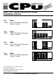
Figure 2b - CPU Switch Multiscreen 4 Port 2 Screen (part code: 32347) Figure 2c - CPU Switch Multiscreen 2 Port 4 Screen (part code: 32348) LINDY CPU Switch Multiscreen Installation and Use Page 10
Figure 2d - CPU Switch Multiscreen 2 Port 2 Screen (part code: 32346) Figure 3 - Remote control pad / display (optional accessory - part 32255) LINDY CPU Switch Multiscreen Installation and Use Page 11
2. Installation 2.1 What you will need Cables to connect the LINDY CPU Switch Multiscreen to each of your PC keyboard, video and mouse ports. Cable specifications are given in appendix A. For convenience we suggest that you connect your keyboard, mouse and first video port using a LINDY 3-in-1 combination cable. Additional video ports may then be connected using video-only cables. Monitors with standard VGA/SVGA (15 pin) connector that will work when connected directly to each of your PCs.
LINDY CPU Switch Multiscreen will operate without a mouse connected if you do not wish to use one. 2.2 Mounting the LINDY CPU Switch Multiscreen The LINDY CPU Switch Multiscreen has been designed for use on a desktop or shelf in close proximity to the user’s monitor and peripherals. The optional remote controller may be used if you wish to locate the LINDY CPU Switch Multiscreen on a desk or shelf that is some distance from the monitor and peripherals. 2.
optional power adapter. When using the optional power adapter, ensure that it is connected to the mains and powering the LINDY CPU Switch Multiscreen before you switch on the connected computers. Failure to switch the LINDY CPU Switch Multiscreen and computers on in the correct order can lead to the mouse and/or keyboard not being recognised by the computers when they are switched on. 2.
To enter configure mode at power on: Switch off all the attached PCs and the LINDY CPU Switch Multiscreen. Hold down the front panel key whilst powering on the LINDY CPU Switch Multiscreen. Remember that the LINDY CPU Switch Multiscreen draws its power from any attached PC via the keyboard cable and so will power itself on when the attached PC is switched on or when the optional power adapter is connected.
L1 - CPU Switch Multiscreen locks on to active ports only during autoscanning (default) L2 - CPU Switch Multiscreen locks on to every port during autoscanning L3 - CPU Switch powers on in autoscan mode and locks on to active ports only L4 - CPU Switch Multiscreen powers on in autoscan mode and locks on to all ports L5 – Allow the mouse to run at any speed (default) L6 – Don't allow the mouse to run at very slow speeds L7 - Cascade query code = AD (default) L8 - Cascade query code = EF T1 - 2 seconds autosca
U7 – Cycle between all ports when switching with ‘Hotkeys + Tab’ or three button mouse (default) U8 – Cycle between active ports only when switching with ‘Hotkeys + Tab’ or three button mouse H1 - Hotkey combination is CTRL + ALT + command key (default) H2 - Hotkey combination is CTRL + SHIFT + command key H3 - Hotkey combination is ALT + SHIFT + command key H4 - Hotkey combination is RIGHT ALT + command key H5 - Hotkey combination is LEFT ALT + RIGHT ALT + command key H6 - Hotkey combination is LEFT CTRL +
2.9 Other useful installation information PC boot up sequence - When your PCs are powered on they communicate with any attached keyboards and mice and setup parameters required by the particular operating system. It is necessary for the LINDY CPU Switch Multiscreen to be attached and powered on during this sequence so that it can give the required responses and keep track of all the modes and settings requested by each of the connected PCs.
key for 5 seconds. When the character ‘C’ is displayed on the front of the LINDY CPU Switch Multiscreen, press the front panel key again. A complete power off reset of the connected keyboards and mice will then be performed. This function only resets the shared keyboard and mice that are plugged into the control port. It does not affect the status of any of the other ports on the switch or the CPU connections. 2.
PC originally booted.
To perform a firmware upgrade on your LINDY CPU Switch Multiscreen you will need a suitable serial upgrade cable and an IBM PC compatible computer with an RS232 serial port and an operating system that supports DOS. Upgrade cables may be purchased for LINDY Technology or may be made using the wiring specification given in Appendix A4. You will also need to download the latest version of the LINDY CPU Switch Multiscreen firmware which is available free of charge at www.lindy.com.
Step 5 - Run the upgrade program The latest version of the LINDY CPU Switch Multiscreen firmware is available from the LINDY Technology website at www.lindy.com. The CPU Switch Multiscreen uses the same firmware as the CPU Switch Smart product. The program and data files are supplied as a pair e.g. CPUSS129.EXE CPUSS129.HEX and should be downloaded to the same directory on your PC. Run the file CPUSSxxx.EXE (e.g. CPUSS129.EXE) and follow the on-screen instructions.
without moving switch 7 from the flash upgrade (ON) position. Switch 7 forces the LINDY CPU Switch Multiscreen into flash upgrade mode and prevents the upgraded code from being run. Running faulty or partially upgraded code may have unpredictable results and may damage your LINDY CPU Switch Multiscreen or computing equipment.
3. Using the LINDY CPU Switch Multiscreen This section explains the general operation of the LINDY CPU Switch Multiscreen. We recommend that you read this section before starting to use the product. 3.1 Power on status At power on the LINDY CPU Switch Multiscreen selects computer 1 and displays ’1’. If a password has been set then ‘P’ will be displayed and the LINDY CPU Switch Multiscreen will remain locked until a valid password is entered. 3.
attached to your keyboard with a couple of Velcro strips to give instant channel information and key control. 3.3 Status display The status display usually shows the currently selected port. If autoscan mode is selected, the segments will illuminate in sequence in a clockwise direction interspersed with a display of the currently selected channel. If LINDY CPU Switch Multiscreen has been locked, ‘P’ will be displayed until a valid password has been typed to unlock the unit.
3.4 Switching operation When you select a port, your keyboard and mouse will control the computer that is connected to that port and the video feeds from that that computer will be displayed on the monitors. For example, if you select channel 2 then the video signal arriving at port 2A will be sent to the monitor that is attached to port A. Video arriving at ports 2B, 2C and 2D will be displayed on the monitors attached to ports B, C and D respectively. 3.
mouse and displays 0. The video signal is switched off. If a password has not been set then the LINDY CPU Switch Multiscreen can be re-enabled by selecting a channel. If a password has been set then the LINDY CPU Switch Multiscreen displays ’P’ to indicate that a valid password must be entered to unlock the switch. Simply type the same key combination as was set during configuration (see section 4.7) followed by the (return) key.
) Hold down centre button ( Press and release left hand button ( ) to select next computer Hold down centre button ( ) Press and release right hand button ( ) to select previous computer 3.7 RS232 control LINDY CPU Switch Multiscreen can be controlled by a remote RS232 device. To select a channel the data rate of the sending device must be set to 1200 baud, 8 bits, no parity and 1 stop bit. No handshaking is used by the LINDY CPU Switch Multiscreen.
For example, consider a situation where two LINDY CPU Switch Multiscreen units are connected together as shown below. To connect to the computer attached to port 3 on LINDY CPU Switch Multiscreen B the user would hold down the hotkey keys then press ‘2’ followed by ‘3’, whilst keeping the hotkey keys pressed. This will have the effect of connecting to port ‘3’ of the LINDY CPU Switch Multiscreen which is connected into port ‘2’ of the first LINDY CPU Switch Multiscreen unit A.
A typical cascade of two LINDY CPU Switch Multiscreens LINDY CPU Switch Multiscreen Installation and Use Page 30
3.9 Synchronising LINDY CPU Switch Multiscreens for multiple video head applications Multiple LINDY CPU Switch Multiscreens may be connected together so that they operate in a synchronised manner. Synchronised operation is useful for applications that require multiple video signals to be switched together. This type of operation is usually required where each computer is fitted with multiple video cards or video cards with multiple video heads.
Synchronised LINDY CPU Switch Multiscreens used to switch eight video channels together LINDY CPU Switch Multiscreen Installation and Use Page 32
4. LINDY CPU Switch Multiscreen configuration options All the options described in this section are entered in LINDY CPU Switch Multiscreen configure mode - see section 2.6 for instructions on entering configure mode. 4.1 Screen saver time delay LINDY CPU Switch Multiscreen contains a programmable screen saver which will blank the display after the set time delay with no keyboard or mouse activity. Simply typing at the keyboard or moving the mouse will re-enable the display.
L1 - CPU Switch Multiscreen only locks on to active ports during autoscanning (default) L2 - CPU Switch Multiscreen locks on to every port in turn during autoscanning L3 - CPU Switch powers on in autoscan mode and locks on to active ports only L4 - CPU Switch Multiscreen powers on in autoscan mode and locks on to all ports T1 - 2 seconds autoscan delay time before switching to next port (default) T2 - 5 seconds autoscan delay time before switching to next port T3 - 7 seconds autoscan delay time before switc
The LINDY CPU Switch Multiscreen supports ‘Internet Mice’ that are compatible with the Microsoft IntelliMouse. These are fitted with a wheel or other scroll control and sometimes have additional buttons. Examples are: LINDY mice Microsoft IntelliMouse Logitech Pilot Mouse + Logitech MouseMan+ Genius NetMouse Genius NetMouse Pro Standard PS/2 and IntelliMouse compatible mice can be connected to the control port.
again). The following keyboard hotkey combinations can be selected. These hotkey combinations are used together with the command keys to trigger the required CPU Switch function. The left and right ALT key combination is particularly suitable for extended keyboards where additional keys can be programmed to act as a combination of other keys. Such keyboards are supplied with some Gateway 2000 computers.
options ) I and ) I to restore mouse function on disconnected PS/2 CPU mouse connections. F1 - Display firmware first digit (Note: F1 is ) followed by NOT O) F2 - Display firmware second digit F3 - Display firmware third digit F5 - Restore PS/2 mouse function to the currently selected CPU’s mouse port F6 - Restore IntelliMouse function to the currently selected CPU’s mouse port F8 - Reset all configurations to factory default settings.
4.8 Cascade query code The LINDY CPU Switch Multiscreens use a special ‘query code’ to detect whether or not they are connected to another LINDY CPU Switch Multiscreen. By default your LINDY CPU Switch Multiscreen uses query code AD. LINDY CPU Switch Junior OSD (another range of keyboard / mouse / video switches from LINDY) units with firmware versions less than 1.09 used query code EF.
4.10 Exit configure mode When you have finished configuring any special options, simply type ‘E’ followed by (return) to exit configure mode and return to normal operation mode. The attached computers can now be switched on.
Appendix A. Cable and connector specifications IMPORTANT NOTE The maximum cable lengths supported vary widely between devices and cables. It may be possible to use cables that are longer than those specified below with certain PCs and peripherals but this cannot be guaranteed. If you experience problems try using shorter cables. A1. Keyboard, monitor and mouse to LINDY CPU Switch Multiscreen All of the shared devices plug directly into the relevant ports at the rear of the LINDY CPU Switch Multiscreen.
cables have these DDC lines connected. Keyboard and PS/2 mice - 6 pin mini-DIN male connector to 6 pin mini-DIN male connector with all lines connected straight through (1-1,2-2 etc.). If the PC has a 5pin DIN AT style keyboard connector you will need a PS/2 to AT keyboard adapter 6-pin mini-DIN female to 5-pin DIN male (readily available). For ‘interface powered’ operation without the optional power adapter the cables should be no longer than 5 metres (see section 2.4 for more details).
Recommended cables: 3-in-1 keyboard, video and mouse combination cable - For convenience, neatness and high video quality we recommend the LINDY brand 3-in-1 combination cables for the keyboard, mouse and first video head connection. For the additional video connections we recommend high quality LINDY tri-coax video cables. LINDY cables are available in various different lengths to suit your requirements. Please quote the following part codes when ordering from your supplier.
Premium Gold S-VGA Cable – Premium Gold S-VGA cable is designed for the highest quality monitor applications, including CAD, DTP and Multimedia installations when preservation of display quality is a major consideration.
A.4 Flash upgrade cable connection The cable connections shown below are to connect either COM1 or COM2 of a PC to the LINDY CPU Switch Multiscreen to allow flash upgrades. A.5 RS232 synchronisation cable pin assignments The cable connections shown below are to connect two LINDY CPU Switch Multiscreens together for synchronised operation (see section 3.
Appendix B. Problem Solving Problem: Poor video quality with smearing fuzziness or ripple. Action: Use screened coaxial video cables to connect your devices. Problem: Mouse does not move cursor on screen. Action: Ensure that the mouse and computer are both connected to LINDY CPU Switch Multiscreen before power is connected and ensure that the LINDY CPU Switch Multiscreen is powered on before the attached computer.