KVM Extender C5 PRO-300 English User Manual LINDY No. 39394 www.lindy.
English Manual About this manual LINDY KVM Extender C5 PRO-300 - Installation and Use First Edition (September 2005) (c) 2005 LINDY Elektronik GmbH. www.lindy.com All rights reserved. Whilst every precaution has been taken in the preparation of this manual, LINDY Electronics Ltd assumes no responsibility for errors or omissions. Neither is any liability assumed for damages resulting from the use of the information contained herein.
English Manual Contents 1. Introduction........................................................................................................5 1.1 Supplied items............................................................................................................. 6 2. Installation......................................................................................................... 7 2.1 Extender C5 configuration switch settings..................................................................
English Manual 5. Special Configuration....................................................................................... 16 5.1 Configuration.............................................................................................................. 16 5.2 What are hotkeys? ...................................................................................................... 16 5.3 Configuration mode....................................................................................................
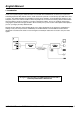
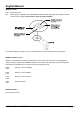
English Manual 1. Introduction Thank you for purchasing the LINDY Extender C5 PRO-300. This KVM Extender set allows you to place the controlling keyboard, video monitor, mouse, audio accessories (and also a serial device) up to 300 metres from a system. The LINDY Extender C5 PRO-300 set consists of two modules: a local module that attaches to your computer system and a remote module to which the peripherals are connected.
English Manual 1.
English Manual 2.
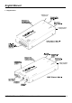
English Manual 2.1 Configuration switch settings The basic operations of the LOCAL and REMOTE modules are controlled by the banks of four switches located on the side of each module. The switches are monitored at all times and may be changed when power is on or off (the only exception to this rule is switch 1 of the LOCAL module which initiates slightly different functions depending on the power state when it is switched).
English Manual REMOTE Switch 1 OFF: ON: Normal operation. (Before power is applied) Places the REMOTE module into flash upgrade mode so that the internal software can be changed. (See section 6. Flash upgrade procedure) Note: When shipped, all switches are set in the OFF positions and this will produce normal operation. REMOTE Switches 2 and 3 Switches 2 and 3 determine which two keyboard keys (when pressed in unison) are to be designated as ‘hotkeys’.
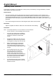
English Manual 2.2 Mounting a module – desk or rack The Extender C5 modules can be situated on a desk (or floor) or alternatively, for larger installations, mounted within optional rack mount chassis units. General remark For correct operation, the local and remote units must have ground connections: At the computer end, ensure that the computer or KVM switch that the LOCAL module is connected to has a ground connection.
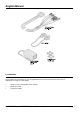
English Manual 3. Connections The naming of the LOCAL and REMOTE modules relate to their proximity to the computer system. Hence, the LOCAL module connects directly to the system, while the REMOTE is at the other end of the twisted pair cable and attaches to the keyboard, mouse, etc. Connections at the LOCAL module 3.1 KVM+A multi-cable connection Most of the connections between the computer system and the LOCAL module are made via the supplied multicable.
English Manual 3.2 Serial cable connection The Extender C5 set offers the option to attach an RS232 serial device (such as a touch screen input) via the remote link. The link supports software or hardware handshaking up to a maximum baud rate of 56 Kb/s. To make the serial connection between the LOCAL module and your computer system, use the supplied serial link cable. 1 2 Attach the male connector of the serial link cable to the 9 pin port on the LOCAL module.
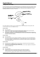
English Manual Connections at the REMOTE module 3.4 Keyboard, video and mouse connections The connections to the keyboard, video monitor and mouse are all made to the sockets at one end of the REMOTE module. 1 2 3 Attach the lead from the monitor to the blue D-type socket on the REMOTE module. Connect the keyboard lead to the purple mini-DIN socket on the REMOTE module. Insert the keyboard lead into the green mini-DIN socket on the REMOTE module. 3.
English Manual 3.6 Audio connections Audio connections are available at the two 3.5” jack sockets mounted on the side (same side as the switch bank) of the REMOTE module. Note: The microphone input has a dual function whereby it can either support a mono-channel microphone or alternatively receive stereo line input. Switch 3 on the LOCAL module controls the setting of this port: LOCAL switch 3 OFF - microphone, LOCAL switch 3 ON - stereo line in.
English Manual 4. Operation 4.1 Power and activity indicators On the front panel of both modules are small recessed indicators which provide confirmation of power and activity, as follows: • Constant red – power applied no communication activity. • Flickering red - power applied, mouse or keyboard activity occurring. • Slow flashing red – module is in flash upgrade mode. Note: Both modules contain internal automatic cut-out fuses to protect against power surges.
English Manual To unlock the system 1 Enter the correct password and press . Note: Passwords are NOT case sensitive. Note: If an invalid password has been entered and the keyboard indicators are not flashing as described above press to clear the incorrect attempt. 2 If the correct password is entered, the screen will be restored and normal operation can continue. To enable the video Simultaneously press the currently configured hotkeys (by default, and along with <1>).
English Manual 5.3 Entering, using and exiting configuration mode To enter and use configuration mode: 1 Simultaneously press the currently configured hotkeys (by default, and ) along with The three keyboard indicators (‘Num Lock’, ‘Caps Lock’ and ‘Scroll Lock’) will now begin to flash in sequence to show that you are in configuration mode.
English Manual 5.5 Password override This mode allows you to override the password that has been set at the REMOTE module and place it into configuration mode so that a new one may be set. This feature is particularly useful when passwords have been lost or forgotten. To override the REMOTE password 1 Remove power from the REMOTE module. 2 With power to the system and LOCAL module still applied, change LOCAL switch 1 to the ON position. 3 Re-apply power to the REMOTE module.
English Manual Recognising an IntelliMouse driver Before hot plugging your Extender C5 (or afterwards using only keyboard control), access the Windows Control Panel and select either the Mouse option (on Windows NT, 2000 and XP) or the System option (on Windows 95, 98, ME). Look for the name of the driver, which will usually include the words PS/2 or IntelliMouse.
English Manual 5.7 Video compensation, Image controls - sharpness and brightness The Extender C5 incorporates special controls to compensate for losses incurred within long cable links. Using these controls you can adjust the picture sharpness and brightness to improve your remote picture quality. The need for image control adjustment is best discovered when viewing high contrast images with vertical edges, such as black lines on a white background.
English Manual If the image controls cannot provide a crisp image If, after adjusting the image controls, the screen image remains fuzzy or has coloured shadows you may need to use the Skew adjustment feature. Please see the next section for details. 5.8 The Skew Compensation Adjustment The twisted pair cabling supported by the Extender C5 set (category 5, or higher) consists of four pairs of cables.
English Manual 4 As appropriate, press either the R, G or B keyboard keys to select the appropriate colour channel. The corresponding keyboard indicators will flash rapidly to show which channel is currently selected for adjustment: Num Lock for Red, Caps Lock for Green and Scroll Lock for Blue. 5 Press the CURSOR LEFT and RIGHT and keys to retard or advance the timing of the selected colour channel respectively.
English Manual 6. Flash upgrade procedure As part of the continual development and improvement process across the range of LINDY products, software upgrades are occasionally made available. The LOCAL and REMOTE modules both contain internal flash memory and LINDY’s unique keyboard-link upgrade technique allows you to utilise software upgrades in a straightforward manner.
English Manual 1 2 3 4 5 Insert a formatted disk into the floppy disk drive. Select ‘Start’, then ‘Settings’ and then ‘Control Panel’. Double click on the ‘Add/Remove Programs’ icon. Select the ‘Startup Disk’ tab. Click ‘Create Disk’ and follow the instructions. To create a startup disk in Windows 95/98 (alternative method) 1 2 3 4 Insert a disk into the floppy disk drive. Right mouse click on the ‘3½ Floppy (A:)’ icon and select ‘Format’.
English Manual 1 Disconnect all cables from the REMOTE module and take it to the computer. 2 Use a ‘KVM switch-type’ keyboard cable (6 pin mini-DIN male to 6 pin mini-DIN male plugs with all lines connected) – not supplied. Attach one end of the cable to the keyboard port of the computer. Connect the other end of the cable to the keyboard port of the REMOTE module. This is the only connection required. 3 On the REMOTE module, change switch 1 to the ON position.
English Manual 7. Troubleshooting If you experience problems when installing or using the Extender C5 modules please check through this section for a possible solution. Video image at the REMOTE module is distorted or shadows appear to the right of displayed objects. Adjustments are required to compensate for the length of the twisted pair cable being used. If video problems persist: • Please refer to ‘Image controls - sharpness and brightness’ section in the ‘Special Configuration’ chapter.
English Manual Sound from the microphone cannot be heard or is very quiet • Check the setting of LOCAL switch 3 – if a microphone is connected at the REMOTE module, the switch should be set to OFF. Sound input from the stereo line input is distorted and only one channel is working • Check the setting of LOCAL switch 3 – if a stereo line input is connected at the REMOTE module, the switch should be set to ON. 8.
Radio Frequency Energy and Compliance Declaration A Category 5 (or better) twisted pair cable must be used to connect the LINDY Extender C5 units in order to maintain compliance with radio frequency energy emission regulations and ensure a suitably high level of immunity to electromagnetic disturbances.