
User Manual


Receiver Connections
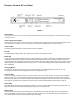
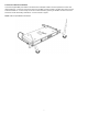
FIGURE 2
Antenna A & B Input Connector (BNC)
Diversity antenna inputs A and B. For correct operation connect the supplied detachable antenna by pressing on the BNC connector
and twisting clockwise for ~1/2 turn. NOTE: Antenna inputs ARE NOT DC biased.
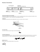
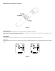
Cable Grip
Thread the power supply cable into the CABLE GRIP to secure the connection as shown in figure 3.
FIGURE 3
DC Power Input
DC socket for connection of power supply, 9V DC 500 mA (supplied).
Instrument Output Jack
This 1/4” unbalanced TRS output jack (1.8 kΩ) is voiced at the tip for instrument applications (gentle high-frequency role off at 8 kHz
approximates sound of a 15’ cable), and full bandwidth (10 Hz to 20 kHz) on the ring. Great for ‘tuner’ out or dual amp setups.
Balanced Low Z
Balanced XLR, 600Ω, full-bandwidth output (10 Hz to 20 kHz).
3