
User Manual
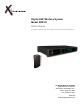


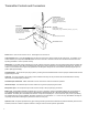


Table Of Contents

Transmitter Controls and Connectors
Power button. Press once to turn the unit on. Press again to turn the unit off.
Channel Select button. Press the CH SEL button to select the next channel. Button sequence will wrap around. For example, once
CH5 is selected you must press the CH SEL button one time to reach CH1. Receiver must be set to the same channel as the corre-
sponding transmitter in order to operate correctly.
LED Display. A blue LED will light indicating the currently selected channel of operation and a
red LED indicates remaining battery life
in one hour increments. When idle, these LEDs toggle continuously. During performance, blue LEDs indicate input level.
There is no
need for a CLIP indicator as the system has greater than 118 dB dynamic range and can accommodate input/output signals up to 6V
peak-to-peak (approximately).
Threaded Sleeve. Secure the 1/8” jack plug in place by screwing down the threaded sleeve onto the input jack socket threads and turn
approximately two times.
Jack Plug. For correct operation, the jack plug must be inserted all the way into the jack socket with the threaded sleeve securely
fastened to the threaded input jack socket.
Threaded Input Jack Socket. Make certain that a secure connection is made for trouble-free operation.
Instrument Input. The instrument input circuit is wired to the ring of the input jack plug and socket.
Microphone Input. The microphone input circuit is wired to the tip of the input jack plug and socket.
Battery Life. Fresh Alkaline batteries should last about ~6 hours in the XDT4. NiCad rechargeable batteries will only last about 3.5
hours. Standard batteries are not recommended. THE BATTERY HOUR DISPLAY WILL ONLY BE ACCURATE FOR ALKALINE
BATTERIES. The battery life is calculated inside the each component and displayed in 1 hour increments. Upon power up the battery
info will take about one minute to stabilize, the battery gauge is then accurate within + or - 15 min. You may use batteries until they are
completely drained without affecting the performance of the unit in any way.
Operation note: the system operates at unity gain meaning that the signal fed to the transmitter is produced identically at the receiver.
Therefore, there are no knobs to adjust or switches to change in order to achieve optimum signal levels.
Jack Plug -
Insert into jack socket.
Cable polarity: ring (+ instrument), sleeve (-), tip (+ mic)
Input
Threaded input jack socket
Channel Select button
LED Display -
A blue LED indicates channel,
red LED indicates battery life.
When idle, these LEDs toggle.
During performance, blue LEDs
indicate input level.
Power button
Threaded Sleeve -
Secure the 1/8” jack plug in
place by screwing down the
threaded sleeve onto the
socket threads approximately
two turns.
3