
Computer Hardware User Manual


Line 6 GearBox 3.7 – Using Your Line 6 Hardware
2•9
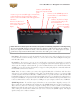
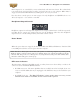
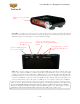
Microphone Input Controls
Rear panel XLR input levels are controlled by a row of Trim knobs on the front panel. Use these inputs
for microphones or balanced input signals with a gain range of 0 dB to 45 dB.
Each XLR input has a -20 dB pad switch, which can be used to provide more headroom for high output
microphones. A 75 Hz cutoff switch is also provided, useful for eliminating low frequency rumble from
microphone sources.
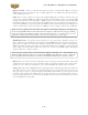
Two +48v phantom power switches are provided for powered mics, such as condenser mics. Phantom
power is distributed via two XLR input banks, permitting the option to run dynamic mics in a non-
powered bank.
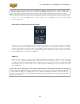
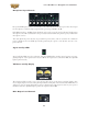
Signal and Clip LEDs
Signal and Clip LEDs exist for each input. The signal LED lights up when signal activity is present,
glowing brighter as the signal level increases. When the input level reaches the 0 dBfs, the clip LED
lights up momentarily.
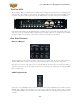
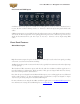
VU Meter and Clip Display
The TonePort UX8 provides a stereo pair of large VU meters on the front panel. By default, these
meters display Inputs 1-2 levels. Using the Inputs & Recording Tab of the Line 6 Audio-MIDI Devices
application, you can assign the hardware meters to display input and output levels of any stereo pair or
GearBox send. The clip LEDs light up when the signal reaches 0 dBfs.
Main Output Level Controls