
User's Manual


8
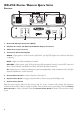
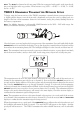
Handheld Transmitter
MUTE SELECT
1. Power / Mute Button – Press briefly to turn on; press and hold for two seconds to turn off. Press
and hold for one second to mute; press briefly to unmute. When in Setup Mode, press this button
to change the value of the parameter one step at a time.
2. Select Button – Press and hold for two seconds to enter Setup Mode; press briefly to go to next
setup page; hold two seconds to exit setup and save changes.
3. LCD Display Panel – Backlight will light briefly when transmitter is turned on and when changing
pages; will stay lit when muted; display also functions as programming window.
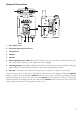
Unscrew the transmitter base and insert two AA batteries. Push the
On/MUTE button to turn on. Press
and hold the
SELECT button for two seconds, and CH and a flashing channel number will appear on
the LCD screen. Press the
On/MUTE button repeatedly in order to change the channel number to
match the receiver. Press and hold the
SELECT button for two seconds to select and return to the main
screen. The transmitter is ready to use.
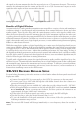
What makes a WiReless digital?
In a typical analog wireless microphone system the signal between the transmitter and the receiver
consists of a very high frequency radio wave carrier that is continually varied slightly in frequency by
the audio signal from the microphone (or other transducer). The electronic circuitry in the receiver
removes the carrier frequency and leaves the audio signal – the same principle that is used in FM radio
broadcasts. The signal is highly compressed upon transmission and expanded at the receiver – the origin
of the word “companding.” Analog transmissions are vulnerable to many interference effects from other
RF and electromagnetic signals – and the interference is usually audible as well as having the effect of
shortening range or rendering the channel unusable.
Input
Signal
(dBu)
+ 25
+ 20
+ 15
+ 10
+ 5
0
- 5
- 10
- 15
- 20
- 25
- 30
- 35
- 40
- 45
- 50
- 55
- 60
- 65
- 70
- 75
- 80
- 85
- 90
+ 25
+ 20
+ 15
+ 10
+ 5
0
- 5
- 10
- 15
- 20
- 25
- 30
- 35
- 40
- 45
- 50
- 55
- 60
- 65
- 70
- 75
- 80
- 85
- 90
Output
Signal
(dBu)
2:1 Compression Ratio
100dB
Dynamic
Range
50dB
Dynamic
Range
Input
Signal
(dBu)
+ 25
+ 20
+ 15
+ 10
+ 5
0
- 5
- 10
- 15
- 20
- 25
- 30
- 35
- 40
- 45
- 50
- 55
- 60
- 65
- 70
- 75
- 80
- 85
- 90
+ 25
+ 20
+ 15
+ 10
+ 5
0
- 5
- 10
- 15
- 20
- 25
- 30
- 35
- 40
- 45
- 50
- 55
- 60
- 65
- 70
- 75
- 80
- 85
- 90
Output
Signal
(dBu)
No Compression
117dB
Dynamic
Range
117dB
Dynamic
Range
Digital wireless microphone systems provide a much more robust and interference resistant performance.
Within the microphone transmitter, the audio signal from the voice or other source is digitally sampled,
and the sample is converted into a digital “word” consisting of the electrical equivalent of a string of
1’s and 0’s. As in analog wireless, a very high frequency carrier wave is modulated, but in this case with
the digital “stream” of samples so that the carrier frequency only has two distinct states that represent