
User's Manual


9
the signal in the same manner that the flat areas and pits on a CD represent the music. The receiver
retrieves this information from the carrier and decodes it via a D/A converter and outputs an audio
signal that is the replica of what was encoded at the mic.
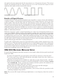
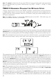
Analog signal with noise Digital signal with noise
Benefits of Digital Wireless
As mentioned above, analog wireless transmissions are susceptible to a variety of noise and interference
conditions, related to signal strength and/or interference from external electronic devices and other
wireless signals. These can ride along with the carrier frequency and its audio signal as added noise,
affect the receiver directly because the antennas that pick up the transmitter signal are also wide open
to pick up other radio signal in the same general RF band, or interact with the carrier frequency to create
additional harmonic frequencies. Problems can come from sources as diverse as a television broadcast
signal, other wireless mics in use, digital signal processors, or even malfunctioning fluorescent lighting
ballasts or other electrical devices.
While the same physics applies to a digital signal riding on a carrier wave, the digital signal with just two
states is more difficult to damage. If the receiver finds that something has come in that is not equivalent
to a digital word of 1’s and 0’s, that information will be ignored. If noise is riding on those digital words,
it is still decoded as one of two states – rather than something in-between, if it were analog. As long as
the digitally modulated carrier arrives at the receiver’s antenna with sufficient level, it will be accurately
decoded. And as with CD players and other digital audio devices, error concealment algorithms may be
added to fill in the gaps where there is missing information.
Typically with a digital wireless system, the signal will retain its quality until the signal level is too low,
and then it’s gone. The main effect that interference has on a digital wireless system is that it will shorten
the maximum range between the transmitter and receiver antenna. To alleviate potential problems,
maintain line-of-sight between transmitter and receiver, locate the receiver / receiver antennas at a
distance from interfering sources such as WiFi routers.
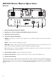
Xd-V55 ReceiVeR detailed setuP
For stand-alone placement, position the receiver on a level surface where the front-panel controls and
displays are visible.
•Connect the supplied DC-1g power supply to the 9 VDC In connector on the rear panel.
•To secure, press a loop of the cable through the cable holder located above the connector to
prevent accidental disconnection.
•Plug the power supply into an available AC outlet that provides voltage from 90 – 240 VAC.
•Place the supplied half-wave antennas on the left and right BNC connectors marked A
ntenna
A and Antenna B. Rotate a quarter-turn clockwise, and then position the antennas at an
approximately 45 degree “rabbit ears” orientation.
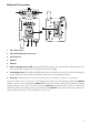
•On the right side of the front panel, turn on the power switch; the LED will light.
•Turn the encoder to select the desired channel, from 1 to 12.
•To sync the handheld or Bodypack transmitter to the receiver, follow the procedure in the
following transmitter setup sections.
Note: The receiver’s RF channel will change immediately to a new frequency when the encoder is
turned.