® XD-V75 Digital Wireless Pilot’s Handbook Manuel de pilotage Pilotenhandbuch Pilotenhandboek Manual del Piloto 取扱説明書 40-00-0330 also available @ www.line6.
Important Safety Instructions C A UT I O N RISK OF ELECTRIC SHOCK DO NOT OPEN WARNING : TO REDUCE THE RISK OF FIRE OR ELECTRIC SHOCK, DO NOT REMOVE SCREWS. NO USER-SERVICEABLE PARTS INSIDE. REFER SERVICING TO QUALIFIED SERVICE PERSONNEL. WARNING : TO REDUCE THE RISK OF FIRE OR ELECTRIC SHOCK, DO NOT EXPOSE THE APPLIANCE TO RAIN OR MOISTURE. CERTIFICATION THIS DEVICE COMPLIES WITH PART 15 OF THE FCC RULES.
You should read these Important Safety Instructions. Keep these instructions in a safe place Before using your XD-V75 Digital Wireless System, carefully read the applicable items of these operating instructions and the safety suggestions. 1. Obey all warnings in the XD-V75 manual. 2. Do not perform service operations beyond those described in the XD-V75 Manual.
Thank you for your purchase of the XD-V75 Digital Wireless microphone system. It is a sophisticated digital wireless system, yet is easy to configure and use within minutes. With its fully digital transmission, the system provides features and benefits that differ in some ways from previous generations of analog wireless, but in most respects you use it just like other wireless systems.
Recommendations for Best Performance • Maintain a clear line of sight between the transmitter and receiver antennas. Typically the receiver antennas should be above head level. Avoid placing the receiver in the bottom of the rack unless remote antennas are employed. • Avoid placing the receiver behind walls. When this is necessary the receiver’s antennas should be remotely located as to be in sight of the transmitter.
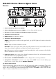
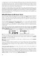
XD-V75 Digital Wireless Quick Setup Receiver 1 2 ANTENNA A A OUT 3 4 5 MAIN OUTS B OUT ANTENNA B USB UNBAL AUDIO BATTERY MUTE TRANSMITTER STATUS BALANCED 9VDC IN PUSH TO SET RF CH 1:THH12 8:00 XD2.4GHz DIGITAL WIRELESS SYSTEM 6 7 8 9 10 1. Antenna A & B Input Connectors (BNC) 2. Antenna A & B Output Connectors (BNC) – to daisy-chain multiple receivers 3. Unbalanced 1/4-Inch and Balanced XLR Audio Output Connectors 4. 9VDC Power Input Connector 5.
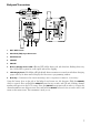
Beltpack Transmitter 6 3 MUTE AUDIO 1 OFF/ON AUDIO Pat. Pending Made in China Designed in U.S.A. 7 008WWA090153 8 FCC ID: UOB916TBP12 IC: 6768A-916TBP12 N222 BATT BATT 4 5 2 1. ON / OFF Switch 2. Mini-XLR (TA4) Input Connector 3. MUTE Switch 4. SELECT 5. VALUE 6. Battery & Audio Status LEDs – Battery LED is blue when good, red when low, flashing when very low; Audio LED is green for audio signal and red for clipping. 7.
MUTE SELECT Handheld Transmitter 1. Power / Mute Button – Press briefly to turn on; press and hold for two seconds to turn off. Press and hold for one second to mute; press briefly to unmute. When in Setup Mode, press this button to change the value of the parameter one step at a time. 2. Select Button – Press and hold for two seconds to enter Setup Mode; press briefly to go to next setup page; hold two seconds to exit setup and save changes. 3.
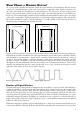
What Makes a Wireless Digital? In a typical analog wireless microphone system the signal between the transmitter and the receiver consists of a very high frequency radio wave carrier that is continually varied slightly in frequency by the audio signal from the microphone (or other transducer). The electronic circuitry in the receiver removes the carrier frequency and leaves the audio signal – the same principle that is used in FM radio broadcasts.
to a digital word of 1’s and 0’s, that information will be ignored. If noise is riding on those digital words, it is still decoded as one of two states – rather than something in-between, if it were analog. As long as the digitally modulated carrier arrives at the receiver’s antenna with sufficient level, it will be accurately decoded. And as with CD players and other digital audio devices, error concealment algorithms may be added to fill in the gaps where there is missing information.
THH12 Handheld Transmitter Detailed Setup To begin, twist the bottom section of the THH12 transmitter counterclockwise, unscrew and remove it. Lightly pull the battery cover tab down with a thumbnail, and open the cover by pulling back; it is hinged at the base of the transmitter. Insert two AA batteries, noting the polarity markings shown in the battery compartment. Note, Use alkaline batteries, or rechargeable NiMH batteries in the 2400 – 2800 mAh range.
Note, The transmitter can be locked so that the user cannot accidentally or deliberately make changes to its settings during use. To set the lock, unscrew the bottom section of the transmitter, go to the back side of the battery compartment, and flip the small micro-switch to the right to lock; the display will show the image of a lock in the lower left corner, and the word [LOCKED] will appear whenever a button is pushed. Replace the bottom section to use.
When the transmitter is on, a quick push and hold of the MUTE button will mute the audio, and the backlight will remain lit while it is muted. The word [MUTE] will appear on the display. Another quick push will un-mute it. The TBP12 transmitter has other editable functions, including high and low power modes, selectable microphone settings, encryption options, and the ability to give the transmitter a 6-character name that will show on both the transmitter and receiver displays.
Channel Scanning Procedure Though the Line 6 wireless microphone system operates in the unlicensed 2.4 GHz band – above the frequencies used by most wireless microphone systems, cellular phones, and other voice communication devices – the band is not unused, and does include WiFi routers.
Note: Make sure all powered on Line6 TX units are a minimum of 2 meters away from scanning RX antennas. This will avoid overload and incorrect scanning function while in this mode. Audio Output & Filter Adjustments Receiver Output Level Adjustments The default receiver output from the XD-V75 receiver is +0 dB or unity gain. This allows the wireless unit to use the same mixer gain levels as the equivalent wired microphone, and connect to the mic-level input of the mixer.
Dynamic Filter Adjustments The dynamic filter allows users to select from [OFF] (no filtering), [NORM] (for music applications), and [TALK] (for spoken word applications). When active, the filter minimizes handling noise and stage vibrations, via a downward expander with a dynamic high-pass filter. In the [NORM] mode, when the microphone input level falls below a fixed threshold, overall level is reduced by approximately 6 dB while simultaneously rolling off frequencies below 200 Hz.
Note, In a production using both wired and wireless microphones, the modeling allows the user to select a wireless mic model that is similar to the majority of wired ones. This selection should help reduce potential feedback from dissimilar microphone frequency responses when using global EQ settings on the audio system. *All product names herein are trademarks of their respective owners, which are in no way associated or affiliated with Line 6.
at usable levels – and the transmitter’s EQ response models will help the process. Try to maintain a constant distance and relationship between the user’s mouth and the microphone. In live theatre this is often done by placing a small mic in the hairline toward the front side of the head or right above the ear. With mic placement on the collar or shoulder area, changes in level can occur as the user’s head turns; experiment with the location of the mic to minimize this effect.
transmitted to the receiver and displayed on the receiver LCD main page. Transmitter Power Level Select The Line 6 digital transmitters give the option to select a lower power transmission, which is useful for minimizing interference when using them along with WiFi or other 2.4 GHz devices, and for extending battery life when the transmitters are used closer to the receiver antennas.
To lock the TBP12 beltpack, turn it on and check the settings, and check the receiver display for signal. With two fingers, press the SELECT and VALUE buttons at the same time and hold for two seconds. The word [LOCKED] will appear on the top line of the display for a moment, and then revert to the main screen. Test by pressing any of the buttons to assure that it is locked. Locking will also temporarily disable the OFF/ON switch. To unlock, again hold the SELECT and VALUE buttons for two seconds.
MUTE SELECT Scroll with the ROTARY ENCODER to go to [MODE: AUTO SENSE / NEW KEY 1: xxxxxx], with the cursor underlining the letter A. If you need to go to [NEW KEY 2], pressing the ROTARY ENCODER once more will advance the cursor to the number 1, and turning the encoder will go to number 2. Pressing the ROTARY ENCODER one more time will advance it to the first character of the six-digit code, which will flash and change as the encoder is turned.
previous code. Then hold SELECT to re-enter setup mode, go to [CRYPTO], and select [ON] again. Follow the same procedure as before to view the code on the transmitter and transfer it automatically or manually to the receiver. During the operation of the system, if the receiver is receiving a signal from a transmitter that is encrypted, and the matching code has been stored, a lower-case letter c will appear on the upper right corner of the display.
Range and Interference Testing The frequency scanning capability of the XD-V75 receiver, plus the A / B antenna metering on the display and the RF LED ladder, provide powerful tools for selecting the clearest channels, avoiding interference, and preventing the wireless microphone systems from interfering with other wireless devices. Using these functions before operating the systems in new locations will ensure trouble-free and compatible performance.
Since the XD-V75 transmitters use two frequencies simultaneously, the bars to the left of each letter represent the lower of the two frequencies, and the bars to the right of each letter the higher frequency. In some cases, only one of the two frequencies will show interference. The following chart describes the potential effect on performance.
at least a few feet away from the receivers when you are operating the wireless system. Minimizing Near / Far Transmitter Effects Line 6 digital wireless systems are designed so that a receiver only passes audio from a transmitter that is set to the same channel. While other nearby transmitters and RF sources will not create audio in a receiver not on their channel, under certain conditions they can have an effect on range.
To rack-mount a single XD-V75 receiver, use both the long and short rack ears provided with the receiver; the receiver can be mounted on either the left or right side of the rack. If you are not using optional remote antennas, you will be mounting the provided half-wave antennas on the long rack ear. Remove the rubber covers to expose the D-cut mounting holes in the rack ear, unthread the hex nut and lock washer from the provided BNC-to-BNC connectors, pass them through the holes, and rethread and tighten.
Note, For best performance, Line 6 recommends that no more than four receivers share a single pair of antennas via looping through the BNC ports on the rear of the receiver. For the next group of four receivers, use another pair of antennas. Alternately, use a Line 6 antenna distribution unit or other RF distribution unit that is appropriate to the 2.4 GHz band to run multiple receivers from one pair of antennas.
APPENDICES Troubleshooting Problem Solution No Audio Switch on transmitter and/or receiver Change transmitter batteries Confirm proper polarity of batteries in transmitter Transmitter audio muted; press MUTE button to unmute Transmitter and receiver are on different channels; set to same channel Transmitter encrypted and receiver not (or with different encryption code) Receiver currently in Channel Scan or Channel Select mode Receiver not connected to audio system, or audio system off or muted Transmitt
Channel RF Frequency Chart The following chart shows the frequencies used by Channels 1 through 14. Each channel uses two frequencies for greater reliability and redundancy. These frequencies are compatible with each other, and chosen to work within an environment where WiFi is running. For best performance, do not place receivers or transmitters in close proximity to WiFi routers or computers.
XD-V75 Digital Wireless System Specifications System Frequency Band 2.4GHz ISM Band Compatible Channels 14 True Diversity Yes Frequency Diversity Yes (2 Frequencies per channel) Compander-Free Design Yes Frequency Response THD % 10 Hz (-0.5 dB) - 20kHz (-2.5 dB) 0.03% typical System Latency < 2.
Transmitters Transmitter RF Output Power 10 mW HI; 3.3 mW LO Battery Life 8 hours Mic Modeling THH12 Handheld TBP12 Beltpack Yes (10 selectable models) Yes (9 selectable EQ filters) Batteries 2 x AA Alkaline Battery Display (on Transmitter) LCD Screen Dynamic Range THH12 Handheld TBP12 Beltpack >115 dB >120 dB TBP12 Maximum Audio Input Level 6.5 Vpp TBP12 Beltpack Input Impedance 1.