
User Manual


6
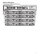
Setting up AntennAS
The XD-AD8 allows multiple wireless receivers to share a single pair of remote antennas, achieving the
same RF signal level and isolation possible with individual pairs of remote antennas connected to each
receiver.
•Mount the XD-AD8 in a rack.
•Attach one end of a BNC-to-BNC antenna cable (provided with the digital wireless
microphone system) to position 1 of the
Antenna A Distribution Connectors on the rear
panel, and attach the other end to the
Antenna A input on the digital wireless receiver.
•Attach a second BNC-to-BNC cable similarly between position 1 of the
Antenna B
Distribution Connectors, and then to the Antenna B input on the same receiver.
•Continue in this manner for the other digital wireless receivers.
•Attach the BNC cable / connector from a remote antenna (P180 directional or P360
omnidirectional) to the
In A BNC connector on the rear panel – the stand-alone BNC
connector on the left side of the XD-AD8. The antenna will be mounted remotely in line-
of-sight with the area where the transmitters will be used. Attach the second remote antenna
similarly to the stand-alone In B connector on the right.
•Attach the IEC power cable to the XD-AD8 and to a 90V – 260V, 50 or 60 Hz AC power
source.
•Turn on the
Power switch on the front panel; the blue LED will light when the unit is on.
•Check that the power LEDs are lit on the P180 or P360 remote antennas.
SeleCting Front or reAr AntennAS
Antenna connections are provided on both the front and rear panels of the XD-AD8, with a selector
switch that determines which connection is active. Remote antennas will typically be connected to
the rear panel
In A and In B connectors, but also can be connected to the front panel. Articulating
half-wave antennas, such as the ones supplied with the Line 6 wireless receivers, can also be used on the
front panel connectors.
•When using remote antennas, connect them to the rear panel
In A and In B BNC connectors,
especially for more permanent installations, as they will be more protected.
•For convenience in portable applications, remote antennas may also be attached to the
Front
Antenna A and B BNC connector.
•Position the front-panel
Antenna Select switch appropriately to Back or Front, depending on
where the antennas are connected.
•If you are using a pair of articulating half-wave antennas supplied with the wireless receivers,
attach them to the front-panel connectors and position in a “rabbit ear” configuration. Slide
the switch to
Front, and make sure the XD-AD8 is positioned near the top of the rack and the
antennas are line-of-sight with the transmitters for the best performance.
Note, Connecting antennas to both front and rear antenna inputs at the same time is not recommended.
Note, When viewing the XD-AD8 from the rear, antenna In A is on the left and In B is on the right.
This placement corresponds with the front-panel connector placement of
A on the right and B on the
left.