
Datasheet


LT4356
4
spikes, generated by the M OSFET itself.
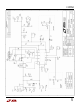
To protect the LT4356-2 from damage during bench
testing with fast-rising input edges, an SM AJ58A Tran-
sZorb has been chosen for diode clamp DCL. This
component clamps the drain spike to less than 100V.
The knee is around 64V. If a dc voltage higher than
60V is connected to D C1018B-B, DCL will be de-
stroyed. Transients to 80V are permissible as the cur-
rent in DCL will be limited by wiring inductance. Fur-
ther, the energy is limited because the time spent in
conduction by DCL is short.
Basic Operation
Connect a 12V supply to input, and the load to output.
The circuit will turn on automatically when power is
applied.
To test the voltage limiter, apply a transient to the 12V
Input. One method of coupling a transient without
backfeeding the 12V supply is shown in the Connection
Diagram, attached. If the input transient is short the
output simply limits at 16V and then recovers to 12V.
If the transient is sustained, the output will rise to 16V,
regulate there and then shut down. The exact timing
and the dividing line between "short" and "sustained" is
a function of the input waveform amplitude and shape
(see the data sheet). Once the input voltage falls below
the Overvoltage Lockout level, autoretry is initiated af-
ter a cooldown period of 42.5ms. The timing intervals
are controlled by CTM R and the TM R pin according to
equations in the data sheet.
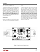
Figure 1
: Proper M easurement Equipment Setup