
Datasheet

LTC2450
9
2450fb
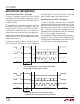
During the data output operation the CS input pin must
be pulled low (CS = LOW). The data output process starts
with the most signifi cant bit of the result being present
at the SDO output pin (SDO = D15) once CS goes low. A
new data bit appears at the SDO output pin following every
falling edge detected at the SCK input pin. The output data
can be latched by the user using the rising edge of SCK.
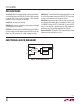
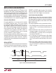
Conversion Status Monitor
For certain applications, the user may wish to monitor
the LTC2450 conversion status. This can be achieved
by holding SCK HIGH during the conversion cycle. In
this condition, whenever the CS input pin is pulled low
(CS = LOW), the SDO output pin will provide an indication
of the conversion status. SDO = HIGH is an indication of
a conversion cycle in progress while SDO = LOW is an
indication of a completed conversion cycle. An example
of such a sequence is shown in Figure 4.
Conversion status monitoring, while possible, is not re-
quired for LTC2450 as its conversion time is fi xed and equal
at approximately 33.3ms (42ms maximum). Therefore,
external timing can be used to determine the completion of a
conversion cycle.
SERIAL INTERFACE
The LTC2450 transmits the conversion result and receives
the start of conversion command through a synchronous
3-wire interface. This interface can be used during the
APPLICATIONS INFORMATION
CONVERT and SLEEP states to assess the conversion
status and during the DATA OUTPUT state to read the
conversion result, and to trigger a new conversion.
Serial Interface Operation Modes
The following are a few of the more common interface
operation examples. Many more valid control and serial
data output operation sequences can be constructed based
upon the above description of the function of the three
digital interface pins.
The modes of operation can be summarized as follows:
1) The LTC2450 functions with SCK idle high (commonly
known as CPOL = 1) or idle low (commonly known as
CPOL = 0).
2) After the 16th bit is read, the user can choose one of
two ways to begin a new conversion. First, one can
pull CS high (CS = ↑). Second, one can use a high-low
transition on SCK (SCK = ↓).
3) In a similar vein, at any time during the Data Output
state, pulling CS high (CS = ↑) causes the part to leave
the I/O state, abort the output and begin a new conver-
sion.
4) When SCK = HIGH, it is possible to monitor the conver-
sion status by pulling CS low and watching for SDO to
go low. This feature is available only in the idle-high
(CPOL = 1) mode.
Figure 4. Conversion Status Monitoring Mode
SLEEP
t
1
t
2
SDO
SCK = HI
CONVERT
2450 F03
CS