
Datasheet


LT1173
3
V
SAT
SW
SAT
Voltage, Step-Down Mode V
IN
= 12V, I
SW
= 650mA 1.1 1.5 V
● 1.7 V
A
V
Gain Block Gain R
L
= 100kΩ (Note 3) ● 400 1000 V/V
Current Limit 220Ω to I
LIM
to V
IN
400 mA
Current Limit Temperature Coeff. ● –0.3 %/°C
Switch OFF Leakage Current Measured at SW1 Pin 1 10 µA
V
SW2
Maximum Excursion Below GND I
SW1
≤ 10µA, Switch Off –400 –350 mV
SYMBOL PARAMETER CONDITIONS MIN TYP MAX UNITS
Note 2: The output voltage waveform will exhibit a sawtooth shape due to
the comparator hysteresis. The output voltage on the fixed output versions
will always be within the specified range.
Note 3: 100kΩ resistor connected between a 5V source and the AO pin.
The ● denotes the specifications which apply over the full operating
temperature range.
Note 1: This specification guarantees that both the high and low trip points
of the comparator fall within the 1.20V to 1.30V range.
E
LECTR
IC
AL C CHARA TERIST
ICS
T
A
= 25°C, V
IN
= 3V, unless otherwise noted.
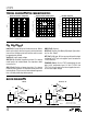
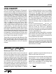
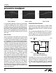
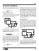
Maximum Switch Current vs Set Pin Bias Current vs Feedback Pin Bias Current vs
R
LIM
Step-Down Mode Temperature Temperature
CCHARA TERIST
ICS
UW
AT
Y
P
I
CA
LPER
F
O
R
C
E
I (A)
0
0
V (V)
0.2
0.4
0.6
1.0
1.2
0.2 0.4 0.6 0.8
LT1173 • TPC01
0.8
1.0 1.2
SWITCH
CESAT
V = 5.0V
IN
V = 3.0V
IN
V = 2.0V
IN
I (A)
0
0.7
SWITCH ON VOLTAGE (V)
0.8
0.9
1.1
1.3
1.4
0.1 0.2 0.3 0.4
LT1173 • TPC02
1.2
0.5 0.6
SWITCH
0.7 0.8
1.0
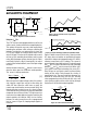
Switch ON Voltage
Saturation Voltage Step-Up Mode Step-Down Mode Maximum Switch Current vs
(SW2 Pin Grounded) (SW1 Pin Connected to V
IN
)R
LIM
Step-Up Mode
TEMPERATURE (°C)
–50
SET PIN BIAS CURRENT (nA)
10
15
20
–25 0 25 50
LT1173 •TPC04
75
100
125
V = 3V
IN
5
TEMPERATURE (°C)
–50
FEEDBACK PIN BIAS CURRENT ( A)
14
16
18
–25 0 25 50
LT1173 •TPC05
75
100
125
V = 3V
IN
µ
12
10
8
R ( )
100
0
SWITCH CURRENT (mA)
400
800
1000
LT1173 • TPC09
Ω
900
700
600
500
300
200
LIM
1000
V
OUT
= 5V
100
V
IN
= 24V
L = 500µH
V
IN
= 12V
L = 250µH
R ( )
10
100
SWITCH CURRENT (mA)
400
800
1200
100
LT1173 • TPC03
Ω
1000
900
700
600
500
300
200
LIM
1000
1100
2V ≤ V
IN
≤ 5V