
Datasheet


LT1173
6
U
S
A
O
PP
L
IC
AT
I
WU
U
I FOR ATIO
LT1173 • TA06
+
–
Ω
SET
V
+12V
+
µ1 F*
µ
1000 F
100
V1 V2
LTC1050
Ω1M
LT1173
CIRCUIT
*NON-POLARIZED
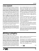
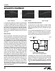
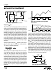
Figure 1. Test Circuit Measures No Load Quiescent Current of
LT1073 Converter
Inductor Selection
A DC-DC converter operates by storing energy as mag-
netic flux in an inductor core, and then switching this
energy into the load. Since it is flux, not charge, that is
stored, the output voltage can be higher, lower, or oppo-
site in polarity to the input voltage by choosing an
appropriate switching topology. To operate as an efficient
energy transfer element, the inductor must fulfill three
requirements. First, the inductance must be low enough
for the inductor to store adequate energy under the worst
case condition of minimum input voltage and switch ON
time. The inductance must also be high enough so that
maximum current ratings of the LT1173 and inductor are
not exceeded at the other worst case condition of maxi-
mum input voltage and ON time. Additionally, the inductor
core must be able to store the required flux; i.e., it must not
saturate
. At power levels generally encountered with
LT1173 based designs, small axial leaded units with
saturation current ratings in the 300mA to 1A range
(depending on application) are adequate. Lastly, the in-
ductor must have sufficiently low DC resistance so that
excessive power is not lost as heat in the windings. An
additional consideration is Electro-Magnetic Interference
(EMI). Toroid and pot core type inductors are recom-
mended in applications where EMI must be kept to a
minimum; for example, where there are sensitive analog
circuitry or transducers nearby. Rod core types are a less
expensive choice where EMI is not a problem.
Specifying a proper inductor for an application requires
first establishing minimum and maximum input voltage,
output voltage, and output current. In a step-up converter,
the inductive events add to the input voltage to produce the
output voltage. Power required from the inductor is deter-
mined by
P
L
= (V
OUT
+ V
D
– V
IN
) (I
OUT
) (02)
where V
D
is the diode drop (0.5V for a 1N5818 Schottky).
Energy required by the inductor per cycle must be equal or
greater than
P
F
L
OSC
03
()
in order for the converter to regulate the output.
When the switch is closed, current in the inductor builds
according to
It
V
R
e
L
IN
Rt
L
()
=
()
'
–
–'
104
where R' is the sum of the switch equivalent resistance
(0.8Ω typical at 25°C) and the inductor DC resistance.
When the drop across the switch is small compared to V
IN
,
the simple lossless equation
It
V
L
t
L
IN
()
=
()
05
can be used. These equations assume that at t = 0,
inductor current is zero. This situation is called “discon-
tinuous mode operation” in switching regulator parlance.
Setting “t” to the switch ON time from the LT1173 speci-
fication table (typically 23µs) will yield i
PEAK
for a specific
“L” and V
IN
. Once i
PEAK
is known, energy in the inductor at
the end of the switch ON time can be calculated as
ELi
L
PEAK
=
()
1
2
06
2
E
L
must be greater than P
L
/F
OSC
for the converter to deliver
the required power. For best efficiency i
PEAK
should be
kept to 1A or less. Higher switch currents will cause
excessive drop across the switch resulting in reduced
efficiency. In general, switch current should be held to as
low a value as possible in order to keep switch, diode and
inductor losses at a minimum.