
Datasheet


LT1173
8
U
S
A
O
PP
L
IC
AT
I
WU
U
I FOR ATIO
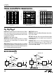
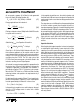
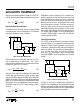
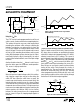
Figure 2. Aluminum Figure 3. Tantalum Figure 4. OS-CON
Note 1: This simple expression neglects the effect of switch and coil
resistance. This is taken into account in the “Inductor Selection” section.
In very low power applications where every microampere
is important, leakage current of the capacitor must be
considered. The OS-CON units do have leakage current in
the 5µA to 10µA range. If the load is also in the microam-
pere range, a leaky capacitor will noticeably decrease
efficiency. In this type application tantalum capacitors are
the best choice, with typical leakage currents in the 1µA to
5µA range.
Diode Selection
Speed, forward drop, and leakage current are the three
main considerations in selecting a catch diode for LT1173
converters. General purpose rectifiers such as the 1N4001
are
unsuitable
for use in
any
switching regulator applica-
tion. Although they are rated at 1A, the switching time of
a 1N4001 is in the 10µs-50µs range. At best, efficiency will
be severely compromised when these diodes are used; at
worst, the circuit may not work at all. Most LT1173 circuits
will be well served by a 1N5818 Schottky diode. The
combination of 500mV forward drop at 1A current, fast
turn ON and turn OFF time, and 4µA to 10µA leakage
current fit nicely with LT1173 requirements. At peak
switch currents of 100mA or less, a 1N4148 signal diode
may be used. This diode has leakage current in the 1nA-
5nA range at 25°C and lower cost than a 1N5818. (You can
also use them to get your circuit up and running, but
beware of destroying the diode at 1A switch currents.) In
situations where the load is intermittent and the LT1173 is
idling most of the time, battery life can sometimes be
extended by using a silicon diode such as the 1N4933,
which can handle 1A but has leakage current of less than
1µA. Efficiency will decrease somewhat compared to a
1N5818 while delivering power, but the lower idle current
may be more important.
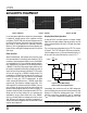
Step-Up (Boost Mode) Operation
A step-up DC-DC converter delivers an output voltage
higher than the input voltage. Step-up converters are
not
short circuit protected since there is a DC path from input
to output.
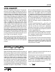
The usual step-up configuration for the LT1173 is shown
in Figure 5. The LT1173 first pulls SW1 low causing V
IN
–
V
CESAT
to appear across L1. A current then builds up in L1.
At the end of the switch ON time the current in L1 is
1
:
i
V
L
t
PEAK
IN
ON
=
()
13
L1
LT1173 • TA10
GND SW2
SW1
LIM
I
IN
V
D1
R3*
LT1173
+
V
OUT
R2
R1
C1
* = OPTIONAL
V
IN
FB
Figure 5. Step-Up Mode Hookup.
Refer to Table 1 for Component Values
Immediately after switch turn off, the SW1 voltage pin
starts to rise because current cannot instantaneously stop
flowing in L1. When the voltage reaches V
OUT
+ V
D
, the
inductor current flows through D1 into C1, increasing
V
OUT
. This action is repeated as needed by the LT1173 to
5 s/DIV
50mV/DIV
LT1173 • TA09
µ
5 s/DIV
50mV/DIV
LT1173 • TA07
µ
5 s/DIV
50mV/DIV
LT1173 • TA08
µ