
Datasheet

3
LT1009 Series
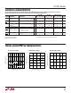
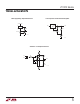
Reverse Characteristics
Forward Characteristics
Reverse Voltage Change
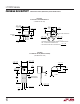
LT1009M LT1009I LT1009/LT1009C
SYMBOL PARAMETER CONDITIONS MIN TYP MAX MIN TYP MAX MIN TYP MAX UNITS
V
Z
Reverse Breakdown T
A
= 25°C, I
R
= 1mA, H, Z Pkg 2.495 2.500 2.505 2.495 2.500 2.505 2.495 2.500 2.505 V
Voltage S Pkg 2.49 2.50 2.51 2.49 2.50 2.51 V
∆V
Z
Reverse Breakdown 400µA ≤ I
R
≤ 10mA 2.6 6 2.6 10 2.6 10 mV
∆I
R
Change with Current ● 3.0 10 3.0 12 3.0 12 mV
r
Z
Reverse Dynamic I
R
= 1mA 0.2 0.6 0.2 1.0 0.2 1.0 Ω
Impedance ● 0.4 1.0 0.4 1.4 0.4 1.4 Ω
Temperature Stability T
MIN
≤ T
A
≤ T
MAX
● 15 15 1.8 4 mV
∆V
Z
Average Temperature 0°C ≤ T
A
≤ 70°C 15 25 15 25 15 25 ppm/°C
∆Temp Coefficient (Notes 2, 3) –40°C ≤ T
A
≤ 85°C 35 ppm/°C
–55°C ≤ T
A
≤ 125°C 25 35 ppm/°C
∆V
Z
Long-Term Stability T
A
= 25°C ±0.1°C 20 20 20 ppm/kHr
∆Time I
R
= 1mA
ELECTRICAL CHARACTERISTICS
TYPICAL PERFORMANCE CHARACTERISTICS
U
W
Note 1: Absolute Maximum Ratings are those values beyond which the life
of a device may be impaired.
Note 2: Guaranteed by Design.
The ● denotes specifications which apply over the full operating temperature range, otherwise specifications are T
A
= 25°C.
For MIL-STD components, please refer to LTC883C data sheet for test listing and parameters.
Note 3: Average temperature coefficient is defined as the total voltage
change divided by the specified temperature change.
REVERSE VOLTAGE (V)
0.5
REVERSE CURRENT (A)
10
–1
10
–2
10
–3
10
–4
10
–5
2.2
1009 G01
1.0
1.4
1.8
2.6
T
J
= 125°C
T
J
= –55°C
T
J
= 25°C
FORWARD CURRENT (mA)
0.001
FORWARD VOLTAGE (V)
1.2
1.0
0.8
0.6
0.4
0.2
0
0.01 0.1 1 10
1009 G02
T
J
= 25°C
REVERSE CURRENT (mA)
0
REVERSE VOLTAGE CHANGE (mV)
5
4
3
2
1
0
16
1009 G03
4
8
12
20