
Datasheet


8
LT1013/LT1014
10134fb
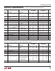
Voltage Gain vs Frequency
FREQUENCY (Hz)
0.01 0.1
VOLTAGE GAIN (dB)
1M 10M
110
100 1k
10k 100k
140
120
100
80
60
40
20
0
–20
V
S
= ±15VV
S
= 5V, 0V
T
A
= 25°C
C
L
= 100pF
1013/14 TPC21
LOAD RESISTANCE TO GROUND (Ω)
100
100k
VOLTAGE GAIN (V/V)
1M
10M
1k 10k
V
O
= 20mV TO 3.5V
WITH V
S
= 5V, 0V
T
A
= 25°C, V
S
= ±15V
T
A
= –55°C, V
S
= ±15V
T
A
= 125°C, V
S
= ±15V
T
A
= –55°C, V
S
= 5V, 0V
T
A
= 25°C, V
S
= 5V, 0V
T
A
= 125°C, V
S
= 5V, 0V
V
O
= ±10V WITH V
S
= ±15V
1013/14 TPC20
Output Short-Circuit Current
vs Time
TIME FROM OUTPUT SHORT TO GROUND (MINUTES)
0
SHORT-CIRCUIT CURRENT (mA)
SINKING SOURCING
12
40
30
20
10
0
–10
–20
–30
–40
3
–55°C
25°C
25°C
125°C
125°C
–55°C
V
S
= ±15V
1013/14 TPC19
Voltage Gain vs Load
Resistance
Single Supply Operation
The LT1013/LT1014 are fully specified for single supply
operation, i.e., when the negative supply is 0V. Input
common mode range includes ground; the output swings
within a few millivolts of ground. Single supply operation,
however, can create special difficulties, both at the input
and at the output. The LT1013/LT1014 have specific
circuitry which addresses these problems.
At the input, the driving signal can fall below 0V— inad-
vertently or on a transient basis. If the input is more than
a few hundred millivolts below ground, two distinct prob-
lems can occur on previous single supply designs, such as
the LM124, LM158, OP-20, OP-21, OP-220, OP-221,
OP-420:
a) When the input is more than a diode drop below ground,
unlimited current will flow from the substrate (V
–
termi-
nal) to the input. This can destroy the unit. On the LT1013/
LT1014, the 400Ω resistors, in series with the input (see
Schematic Diagram), protect the devices even when the
input is 5V below ground.
Gain, Phase vs Frequency
FREQUENCY (MHz)
0.1 0.3
VOLTAGE GAIN (dB)
20
10
0
–10
PHASE SHIFT (DEGREES)
80
100
120
140
160
180
200
13 10
T
A
= 25°C
V
CM
= 0V
C
L
= 100pF
PHASE
±15V
5V, 0V
±15V
5V, 0V
GAIN
1013/14 TPC22
Channel Separation vs
Frequency
FREQUENCY (Hz)
10
CHANNEL SEPARATION (dB)
160
140
120
100
80
60
100k
100
1k
10k
1M
LIMITED BY
THERMAL
INTERACTION
R
S
= 1kΩ
R
S
= 100Ω
V
S
= ±15V
T
A
= 25°C
V
IN
= 20Vp-p to 5kHz
R
L
= 2k
LIMITED BY
PIN TO PIN
CAPACITANCE
1013/14 TPC23
APPLICATIO S I FOR ATIO
WUU
U
TYPICAL PERFOR A CE CHARACTERISTICS
UW