
Datasheet

LT1013/LT1014
10
10134fd
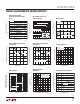
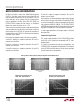
b) When the input is more than 400mV below ground
(at 25°C), the input stage saturates (transistors Q3 and
Q4) and phase reversal occurs at the output. This can
cause lock-up in servo systems. Due to a unique phase
reversal protection circuitry (Q21, Q22, Q27, Q28), the
LT1013/LT1014’s outputs do not reverse, as illustrated
below, even when the inputs are at –1.5V.
There is one circumstance, however, under which the phase
reversal protection circuitry does not function: when the
other op amp on the LT1013, or one specific amplifier of
the other three on the LT1014, is driven hard into negative
saturation at the output.
Phase reversal protection does not work on amplifier:
A when D’s output is in negative saturation. B’s and C’s
outputs have no effect.
B when C’s output is in negative saturation. A’s and D’s
outputs have no effect.
C when B’s output is in negative saturation. A’s and D’s
outputs have no effect.
applicaTions inForMaTion
D when A’s output is negative saturation. B’s and C’s
outputs have no effect.
At the output, the aforementioned single supply designs
either cannot swing to within 600mV of ground (OP-20)
or cannot sink more than a few microamperes while swing-
ing to ground (LM124, LM158). The LT1013/LT1014’s
all-NPN output stage maintains its low output resistance and
high gain characteristics until the output is saturated.
In dual supply operations, the output stage is crossover
distortion-free.
Comparator Applications
The single supply operation of the LT1013/LT1014 lends
itself to its use as a precision comparator with TTL com-
patible output:
In systems using both op amps and comparators, the
LT1013/LT1014 can perform multiple duties; for example,
on the LT1014, two of the devices can be used as op amps
and the other two as comparators.
4V
LT1013/LT1014
NO PHASE REVERSAL
2V
4V
0V
6V
P-P
INPUT, –1.5V TO 4.5V
4V
LM324, LM358, OP-20
EXHIBIT OUTPUT PHASE
REVERSAL
V
S
= 5V, 0V
4
2
0
–100
0
2
0
0
100
INPUT (mV) OUTPUT (V)
INPUT (mV) OUTPUT (V)
Voltage Follower with Input Exceeding the Negative Common Mode Range
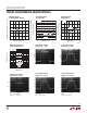
Comparator Rise Response Time
10mV, 5mV, 2mV Overdrives
Comparator Fall Response Time
to 10mV, 5mV, 2mV Overdrives
2V2V
0V0V
4
50µs/DIV
V
S
= 5V, 0V
50µs/DIV