
Datasheet

LT1013/LT1014
9
10134fd
Typical perForMance characTerisTics
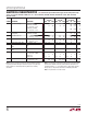
Voltage Gain vs Frequency
FREQUENCY (Hz)
0.01 0.1
VOLTAGE GAIN (dB)
1M 10M
1 10
100 1k
10k 100k
140
120
100
80
60
40
20
0
–20
V
S
= ±15VV
S
= 5V, 0V
T
A
= 25°C
C
L
= 100pF
1013/14 TPC21
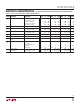
LOAD RESISTANCE TO GROUND (Ω)
100
100k
VOLTAGE GAIN (V/V)
1M
10M
1k 10k
V
O
= 20mV TO 3.5V
WITH V
S
= 5V, 0V
T
A
= 25°C, V
S
= ±15V
T
A
= –55°C, V
S
= ±15V
T
A
= 125°C, V
S
= ±15V
T
A
= –55°C, V
S
= 5V, 0V
T
A
= 25°C, V
S
= 5V, 0V
T
A
= 125°C, V
S
= 5V, 0V
V
O
= ±10V WITH V
S
= ±15V
1013/14 TPC20
Output Short-Circuit Current
vs Time
TIME FROM OUTPUT SHORT TO GROUND (MINUTES)
0
SHORT-CIRCUIT CURRENT (mA)
SINKING SOURCING
1 2
40
30
20
10
0
–10
–20
–30
–40
3
–55°C
25°C
25°C
125°C
125°C
–55°C
V
S
= ±15V
1013/14 TPC19
Voltage Gain vs Load Resistance
Gain, Phase vs Frequency
Channel Separation
vs Frequency
applicaTions inForMaTion
FREQUENCY (MHz)
0.1 0.3
VOLTAGE GAIN (dB)
20
10
0
–10
PHASE SHIFT (DEGREES)
80
100
120
140
160
180
200
1 3 10
T
A
= 25°C
V
CM
= 0V
C
L
= 100pF
PHASE
±15V
5V, 0V
±15V
5V, 0V
GAIN
1013/14 TPC22
FREQUENCY (Hz)
10
CHANNEL SEPARATION (dB)
160
140
120
100
80
60
100k
100
1k
10k
1M
LIMITED BY
THERMAL
INTERACTION
R
S
= 1kΩ
R
S
= 100Ω
V
S
= ±15V
T
A
= 25°C
V
IN
= 20Vp-p to 5kHz
R
L
= 2k
LIMITED BY
PIN TO PIN
CAPACITANCE
1013/14 TPC23
Single Supply Operation
The LT1013/LT1014 are fully specified for single supply
operation, i.e., when the negative supply is 0V. Input
common mode range includes ground; the output swings
within a few millivolts of ground. Single supply operation,
however, can create special difficulties, both at the input
and at the output. The LT1013/LT1014 have specific circuitry
which addresses these problems.
At the input, the driving signal can fall below 0V—in-
advertently or on a transient basis. If the input is more
than a few hundred millivolts below ground, two distinct
problems can occur on previous single supply designs,
such as the LM124, LM158, OP-20, OP-21, OP-220,
OP
-
221, OP-420:
a) When the input is more than a diode drop below
ground, unlimited current will flow from the substrate
(V
–
terminal) to the input. This can destroy the unit. On
the LT1013/LT1014, the 400Ω resistors, in series with the
input (see Schematic Diagram), protect the devices even
when the input is 5V below ground.