
Datasheet


4
LT1019
1019fd
LTC1019A LTC1019
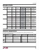
SYMBOL PARAMETER CONDITIONS MIN TYP MAX MIN TYP MAX UNITS
∆V
OUT
Load Regulation Series 0 ≤ I
OUT
≤ 10mA (Note 5) 0.02 0.05 0.02 0.05 mV/mA (Ω)
∆I
OUT
Mode (Notes 4, 5) ● 0.08 0.08 mV/mA (Ω)
Load Regulation, 1mA ≤ I
SHUNT
≤ 10mA (Notes 5, 6)
Shunt Mode 2.5V, 4.5V, 5V
● 0.1 0.4 0.1 0.4 mV/mA (Ω)
10V
● 0.8 0.8 mV/mA (Ω)
Thermal Regulation (Note 7) ∆P = 200mW, t = 50ms 0.1 0.5 0.1 0.5 ppm/mW
I
Q
Quiescent Current 0.65 1.0 0.65 1.2 mA
Series Mode
● 1.3 1.5 mA
Minimum Shunt Current (Note 8) ● 0.5 0.8 0.5 0.8 mA
Minimum Input/Output I
OUT
≤ 1mA ● 0.9 1.1 0.9 1.1 V
Voltage Differential I
OUT
= 10mA ● 1.3 1.3 V
Trim Range LT1019-2.5 ±3.5 ±6 ±3.5 ±6%
LT1019-5 ±3.5 5, –13 ±3.5 5, – 13 %
LT1019-10 ±3.5 5, – 27 ±3.5 5, – 27 %
I
SC
Short-Circuit Current 2V ≤ V
IN
≤ 35V 15 25 50 15 25 50 mA
Output Connected to GND
● 10 10 mA
e
n
Output Voltage Noise 10Hz ≤ f ≤ 1kHz 2.5 4 2.5 4 ppm (RMS)
(Note 10) 0.1Hz ≤ f ≤ 10Hz 2.5 2.5 ppm (P-P)
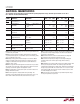
Note 1: Absolute Maximum Ratings are those values beyond which the life
of a device may be impaired.
Note 2: These are high power conditions and are therefore guaranteed
only at temperatures equal to or below 70°C. Input is either floating, tied to
output or held higher than output.
Note 3: Output voltage drift is measured using the box method. Output
voltage is recorded at T
MIN
, 25°C and T
MAX
. The lowest of these three
readings is subtracted from the highest and the resultant difference is
divided by (T
MAX
– T
MIN
).
Note 4: Line regulation and load regulation are measured on a pulse basis
with low duty cycle. Effects due to die heating must be taken into account
separately. See thermal regulation and application section.
Note 5: Load regulation is measured at a point 1/8" below the base of the
package with Kelvin contacts.
Note 6: Shunt regulation is measured with the input floating. This
parameter is also guaranteed with the input connected (V
IN
– V
OUT
) > 1V,
0mA ≤ I
SINK
≤ 10mA. Shunt and sink current flow into the output.
Note 7: Thermal regulation is caused by die temperature gradients created
by load current or input voltage changes. This effect must be added to
normal line or load regulation.
Note 8: Minimum shunt current is measured with shunt voltage held
20mV below the value measured at 1mA shunt current.
Note 9: Minimum input/output voltage is measured by holding input
voltage 0.5V above the nominal output voltage, while measuring
V
IN
– V
OUT
.
Note 10: RMS noise is measured with a single pole highpass filter at 10Hz
and a 2-pole lowpass filter at 1kHz. The resulting output is full-wave
rectified and then integrated for a fixed period, making the final reading an
average as opposed to RMS. A correction factor of 1.1 is used to convert
from average to RMS, and a second correction of 0.88 is used to correct
the nonideal bandpass of the filters.
Note 11: If the part is stored outside of the specified temperature range,
the output may shift due to hysteresis.
E
LECTR
IC
AL C CHARA TERIST
ICS
The ● denotes specifications which apply over the full operating temperature range, otherwise specifications are T
A
= 25°C.
V
IN
= 15V, I
OUT
= 0 unless otherwise noted.