
Datasheet


15
LT1021
Information furnished by Linear Technology Corporation is believed to be accurate and reliable.
However, no responsibility is assumed for its use. Linear Technology Corporation makes no represen-
tation that the interconnection of its circuits as described herein will not infringe on existing patent rights.
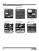
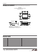
PACKAGE DESCRIPTION
U
Dimensions in inches (millimeters) unless otherwise noted.
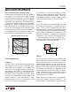
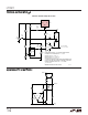
N8 Package
8-Lead PDIP (Narrow 0.300)
(LTC DWG # 05-08-1510)
N8 1098
0.100
(2.54)
BSC
0.065
(1.651)
TYP
0.045 – 0.065
(1.143 – 1.651)
0.130 ± 0.005
(3.302 ± 0.127)
0.020
(0.508)
MIN
0.018 ± 0.003
(0.457 ± 0.076)
0.125
(3.175)
MIN
12
3
4
87 6
5
0.255 ± 0.015*
(6.477 ± 0.381)
0.400*
(10.160)
MAX
0.009 – 0.015
(0.229 – 0.381)
0.300 – 0.325
(7.620 – 8.255)
0.325
+0.035
–0.015
+0.889
–0.381
8.255
()
*THESE DIMENSIONS DO NOT INCLUDE MOLD FLASH OR PROTRUSIONS.
MOLD FLASH OR PROTRUSIONS SHALL NOT EXCEED 0.010 INCH (0.254mm)
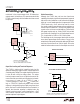
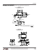
H Package
8-Lead TO-5 Metal Can (0.200 PCD)
(LTC DWG # 05-08-1320)
0.050
(1.270)
MAX
0.016 – 0.021**
(0.406 – 0.533)
0.010 – 0.045*
(0.254 – 1.143)
SEATING
PLANE
0.040
(1.016)
MAX
0.165 – 0.185
(4.191 – 4.699)
GAUGE
PLANE
REFERENCE
PLANE
0.500 – 0.750
(12.700 – 19.050)
0.305 – 0.335
(7.747 – 8.509)
0.335 – 0.370
(8.509 – 9.398)
DIA
0.200
(5.080)
TYP
0.027 – 0.045
(0.686 – 1.143)
0.028 – 0.034
(0.711 – 0.864)
0.110 – 0.160
(2.794 – 4.064)
INSULATING
STANDOFF
45°TYP
H8(TO-5) 0.200 PCD 1197
LEAD DIAMETER IS UNCONTROLLED BETWEEN THE REFERENCE PLANE
AND 0.045" BELOW THE REFERENCE PLANE
FOR SOLDER DIP LEAD FINISH, LEAD DIAMETER IS
0.016 – 0.024
(0.406 – 0.610)
*
**
PIN 1