
Datasheet
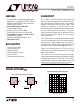

4
LT1021
E
LECTR
IC
AL C CHARA TERIST
ICS
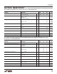
LT1021-10
PARAMETER CONDITIONS MIN TYP MAX UNITS
Output Voltage (Note 2) LT1021C-10 9.995 10.00 10.005 V
LT1021B-10/LT1021D-10 9.950 10.00 10.050 V
Output Voltage Temperature Coefficient (Note 3) T
MIN
≤ T
J
≤ T
MAX
LT1021B-10 ● 2 5 ppm/°C
LT1021C-10/LT1021D-10
● 5 20 ppm/°C
Line Regulation (Note 4) 11.5V ≤ V
IN
≤ 14.5V 1.0 4 ppm/V
● 6 ppm/V
14.5V ≤ V
IN
≤ 40V 0.5 2 ppm/V
● 4 ppm/V
Load Regulation (Sourcing Current) 0 ≤ I
OUT
≤ 10mA 12 25 ppm/mA
(Note 4)
● 40 ppm/mA
Load Regulation (Shunt Mode) 1.7mA ≤ I
SHUNT
≤ 10mA 50 100 ppm/mA
(Notes 4, 5)
● 150 ppm/mA
Supply Current (Series Mode) 1.2 1.7 mA
● 2.0 mA
Minimum Current (Shunt Mode) V
IN
is Open 1.1 1.5 mA
● 1.7 mA
Output Voltage Noise (Note 6) 0.1Hz ≤ f ≤ 10Hz 6.0 µV
P-P
10Hz ≤ f ≤ 1kHz 3.5 6 µV
RMS
Long Term Stability of Output Voltage (Note 7) ∆t = 1000Hrs Noncumulative 15 ppm
Temperature Hysteresis of Output ∆T = ±25°C 5 ppm
Note 1: Absolute Maximum Ratings are those values beyond which the life
of a device may be impaired.
Note 2: Output voltage is measured immediately after turn-on. Changes
due to chip warm-up are typically less than 0.005%.
Note 3: Temperature coefficient is measured by dividing the change in
output voltage over the temperature range by the change in temperature.
Separate tests are done for hot and cold; T
MIN
to 25°C and 25°C to T
MAX
.
Incremental slope is also measured at 25°C.
Note 4: Line and load regulation are measured on a pulse basis. Output
changes due to die temperature change must be taken into account
separately. Package thermal resistance is 150°C/W for TO-5 (H), 130°C/W
for N and 150°C/W for the SO-8.
Note 5: Shunt mode regulation is measured with the input open. With the
input connected, shunt mode current can be reduced to 0mA. Load
regulation will remain the same.
Note 6: RMS noise is measured with a 2-pole highpass filter at 10Hz and a
2-pole lowpass filter at 1kHz. The resulting output is full-wave rectified and
then integrated for a fixed period, making the final reading an average as
opposed to RMS. Correction factors are used to convert from average to
RMS and correct for the non-ideal bandpass of the filters.
Peak-to-peak noise is measured with a single highpass filter at 0.1Hz and a
2-pole lowpass filter at 10Hz. The unit is enclosed in a still-air environment
to eliminate thermocouple effects on the leads. Test time is 10 seconds.
Note 7: Consult factory for units with long term stability data.
The ● denotes specifications that apply over the full operating temperature
range, otherwise specifications are T
A
= 25°C. V
IN
= 15V, I
OUT
= 0, unless otherwise noted.