
Datasheet


1
LT1054/LT1054L
1054lfe
DESCRIPTIO
U
FEATURES
APPLICATIO S
U
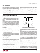
BLOCK DIAGRA
W
Switched-Capacitor Voltage
Converter with Regulator
■
Available in Space Saving SO-8 Package
■
Output Current: 100mA (LT1054)
125mA (LT1054L)
■
Reference and Error Amplifier for Regulation
■
Low Loss: 1.1V at 100mA
■
Operating Range:3.5V to 15V (LT1054)
3.5V to 7V (LT1054L)
■
External Shutdown
■
External Oscillator Synchronization
■
Can Be Paralleled
■
Pin Compatible with the LTC
®
1044/LTC7660
The LT
®
1054 is a monolithic, bipolar, switched-capacitor
voltage converter and regulator. The LT1054 provides
higher output current than previously available converters
with significantly lower voltage losses. An adaptive switch
driver scheme optimizes efficiency over a wide range of
output currents. Total voltage loss at 100mA output current
is typically 1.1V. This holds true over the full supply voltage
range of 3.5V to 15V. Quiescent current is typically 2.5mA.
The LT1054 also provides regulation, a feature not previ-
ously available in switched-capacitor voltage converters.
By adding an external resistive divider a regulated output
can be obtained. This output will be regulated against
changes in both input voltage and output current. The
LT1054 can also be shut down by grounding the feedback
pin. Supply current in shutdown is less than 100µA.
The internal oscillator of the LT1054 runs at a nominal
frequency of 25kHz. The oscillator pin can be used to adjust
the switching frequency or to externally synchronize the
LT1054.
The LT1054 is pin compatible with previous converters
such the LTC1044/LTC7660.
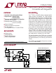
OUTPUT CURRENT (mA)
0
VOLTAGE LOSS (V)
1
2
50
1054 TA01•
0
25
75 100 125
T
J
= 125°C
T
J
= 25°C
T
J
= –55°C
LT1054
LT1054L
3.5V ≤ V
IN
≤ 15V (LT1054)
3.5V ≤ V
IN
≤ 7V (LT1054L)
C
IN
= C
OUT
= 100µF
INDICATES GUARANTEED
TEST POINT
, LTC and LT are registered trademarks of Linear Technology Corporation.
LT1054/LT1054L Voltage Loss
REFERENCE
OSC
DRIVE DRIVE
DRIVE
DRIVE
OSC
CAP
–
GND
CAP
+
FEEDBACK/
SHUTDOWN
–
+
R
R
*EXTERNAL CAPACITORS
2.5V
6
1
4
3
–V
OUT
LT1054 • BD
5
2
8
7
Q
Q
V
REF
C
IN
*
V
IN
C
OUT
*
+
+
■
Voltage Inverter
■
Voltage Regulator
■
Negative Voltage Doubler
■
Positive Voltage Doubler